

Potato Man
Jim Haught
Got your eye out for a simple free-flight (FF) model? We hashed out The Man so it would appeal to you!
The free-flight version of our trio is designed to be simple and rugged, yet have a bit of performance. Potato Man had its genesis in the Grasshopper kit produced by Curt Stevens at Model Research Labs. Curt's idea was to scale up the old Baby ROG rubber-powered design of 50 years ago, add an engine to it (supplied with the kit!), and have a beginner's power model.
I built a Grasshopper for display purposes and saw several fly. While they performed as advertised, I felt the design could be improved and the performance enhanced without making the model difficult to build. So with a nod to Curt, here's The Potato Man — the nickname for our youngest son, Bill. The first time I picked him up, he felt "just like a sack of potatoes!"
Construction
Most of the framework is 3/8" square balsa. Buy about 10 sticks (36" long) and you'll have plenty to pick from and have a few spares on hand.
All wood sizes are stock; I recommend Sig balsa for consistent quality. Virtually all materials needed to build this model (wheels, engine, wire) are available from Sig if you want one-stop shopping.
I recommend Duco cement (available in hardware stores and some discount chains) or an aliphatic-resin-type glue (such as Sig-Bond or Titebond) for basic construction. Except for the firewall, epoxies are too heavy and cyanoacrylates (CyAs) are brittle for this type of structure.
Stabilizer
This is a good place to start because the pieces are easy to handle and construction doesn't take long. It's always easier to complete a model when you can look at part of it that's already finished.
- Lay the plan out on a flat surface that will accept pins (Homasote from building-supply stores is excellent). Cover the working area with plastic food wrap so glue won't stick to it.
- Mark one piece of the outline to length and cut straight through the wood. If you have a small miter box, it's easier to make square cuts; otherwise sand the corners square so you have solid glue joints.
- Pin the first piece in place on the plan and continue marking, cutting, and pinning around the stabilizer perimeter. Carefully cut the center piece for a snug—but not forced—fit between the leading and trailing edges.
- Remove the pieces, glue the joints, and repin in place on the plan. Allow several hours minimum for the glue to dry before removing the stabilizer.
- Give the stab a light sanding with 320- or 400-grit paper to remove glue bumps and smooth everything out. Set the stab framework aside until the wing structure is completed.
Wing
Potato Man features a four-panel (polyhedral) wing. It requires more pieces to assemble and align, but the extra time is worthwhile for improved performance and stability.
- Cut parts for one rectangular panel at a time: build four rectangles rather than trying to cut every part separately. Line up, pin, and glue one rectangle, then proceed to the next until you have four.
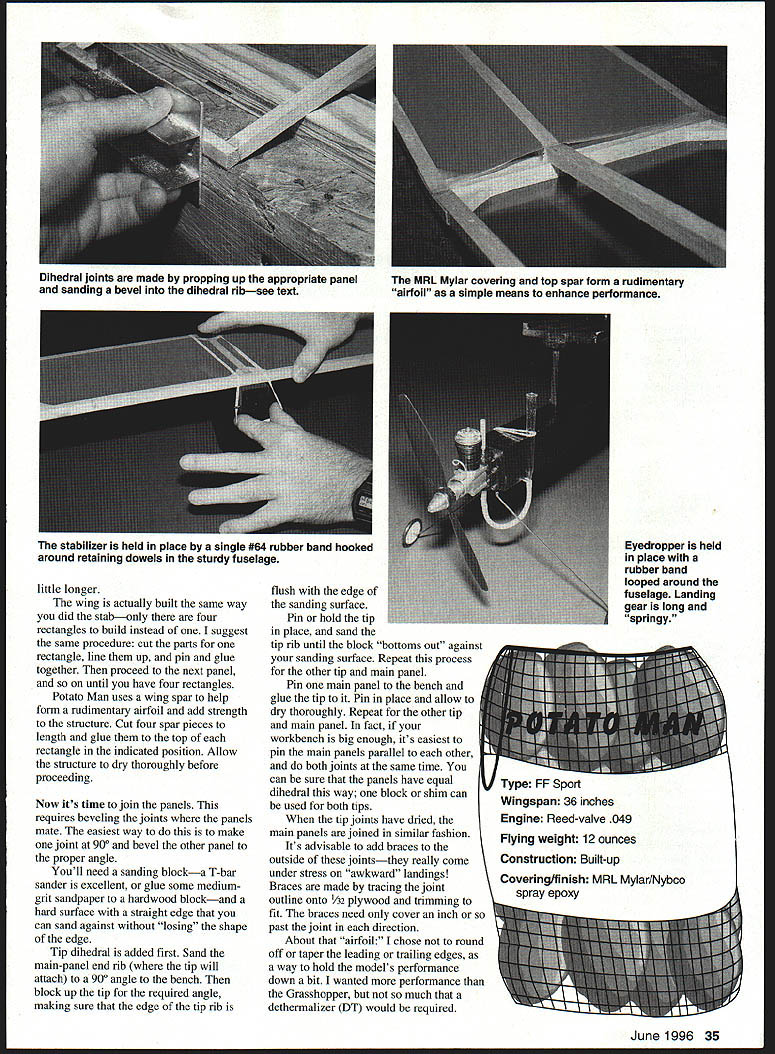
- Cut four spar pieces to the length of each panel and glue them to the top of each rectangle in the indicated position. The spar helps form a rudimentary airfoil and adds strength. Allow to dry thoroughly before joining panels.
- To join panels, bevel the joints so the panels mate. The easiest method is to make one mating edge a true 90° and sand the adjoining edge to the required dihedral angle.
- Use a sanding block or T-bar sander, medium-grit sandpaper, a hardwood block, and a hard straight edge so you don't lose the shape of the edge.
- Add the dihedral first: sand the main-panel end to 90° to the bench, block up the tip to the required angle, and sand the tip rib until the block bottoms out. Repeat for the other tip and main panel.
- Pin the main panel to the bench and glue the tip in place. Allow to dry thoroughly. If your bench is big enough, pin the main panels parallel and glue both tip joints at the same time for equal dihedral, using a block shim between tips.
- When tip joints have dried, join the main panels in a similar fashion.
- Add braces outside the joints; they take stress during awkward landings. Trace the joint outline onto 1/32" plywood and trim to fit. Braces should cover about 1/4" (or roughly an inch in some descriptions) past the joint in each direction.
- About the airfoil: the prototype rounded and tapered the leading and trailing edges to moderate performance so less dethermalizer (DT) would be required. Alternatively, a blunt section will reduce performance even further if you want an easier-to-fly machine. Decide before finishing edges.
Specifications
- Type: FF Sport
- Wingspan: 36"
- Engine: Reed-valve .049
- Flying weight (prototype): about 12 oz (typical)
- Construction: Built-up
- Covering/finish: MRL Mylar / Nybco spray epoxy
Fuselage
The fuselage is a big, sturdy box—designed tough. Light pieces fit together so the pylon and rudder automatically align—one less thing to contend with as you proceed. Build the fuselage right side up.
- Pin the right side to the plan; add bottom, top, and end pieces.
- Use scrap balsa in the pylon slot to hold pieces apart the proper distance. The rudder can be built with the pylon left out and slid back and forth to determine proper center-of-gravity (C.G.) position.
- The landing gear on the prototype is trapped between the firewall and the engine. It's easier to mount the gear so it is removable for straightening if bent. Make the gear intentionally thin and springy for maximum cushioning effect.
- If you lack experience bending music wire, practice on an old coat hanger first—the hanger wire is softer and gives an idea of what to expect. Start wheel-axle work slowly; take care and be patient—it's hard to fix a ruined axle.
Covering/Finish
The prototype's wing and stabilizer were covered with Model Research Labs' iron-on clear Mylar (the same used on the Grasshopper), available in rolls from MRL at 25108 Marguerite #160, Mission Viejo, CA 92692. It's lighter than most iron-on coverings, easier to handle, and clear for unlimited color choices.
- Start with the stabilizer on a small, flat surface. Cut a piece of covering about 1/2" to 1" larger than the perimeter of the stab.
- Set the iron to a medium-heat setting. Test to be sure the material will attach without melting. MRL film's frosty appearance helps you see when the adhesive has activated.
- Use the tip of the iron to tack the film to the top framework—corners first, then center, working progressively in smaller areas. Stay on the wood; do not attempt to shrink open areas yet. Iron the film down around the front edges and trim excess.
- Paint the bottom of the stab and the inside of the area you just covered with a spray enamel. Cheap paint will work because it will be trapped inside the covering and protected from fuel.
- After the paint dries, cover the bottom of the stab with clear Mylar as you did the top. After both surfaces are covered, shrink the open areas smooth and poke a couple of pinholes in each panel to allow ventilation when heat builds.
- The wing covering follows the same method—more pieces, same technique. I didn't add fill-in pieces to the dihedral and tip ribs; the covering is simply wrapped around the ribs and tips and overlapped at the dihedral joints. It may look ugly but it flies fine.
- The fuselage was finished with Nybco spray epoxy on the prototype—good color, fuelproof up to 25% nitro, inexpensive and readily available. Black was used for coverage.
Wing mounting and keys:
- Key the wing to maintain alignment over flights. 1/16" x 5" keys keep the wing on straight but allow some give on cartwheel-type landings; they will slide or shear off and are easy to replace.
- Place a drafting triangle against the side of the pylon, shift the wing until the leading edge is even with the triangle edge as you sight along it, mark where the wing leading and trailing edge contact the wing platform, scrape the covering away at those points, and glue the keys in place.
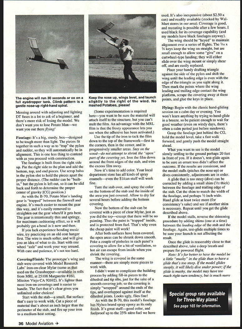
Flying
Begin with classic hand-glide sessions on a calm day or evening. Don't try to hand-glide in a breeze—wait for calm conditions or the brief calm periods near sundown.
- Hold the fuselage just behind the CG, keep the model level, take a fast walk forward, and gently push the model straight ahead.
- You want to see the model slowly settle to the ground perhaps 20 feet in front of you. If it stalls (pitches nose up) or dives consistently, adjust the CG.
- If the glide is too steep (dives), add a small shim (1/32") between the fuselage and the trailing edge of the stab. Cut the shim to match the fuselage width and about 1/2" long. Test-glide repeatedly and add or remove shims until the desired glide is achieved.
- If the model stalls, add shims (one at a time) between the leading edge of the stab and the fuselage.
- It's better to be a little "mushy" in the glide than too steep. A steep glide likely results in a dive under power; a mushy glide is more forgiving but may show a right-turn tendency.
Engine test and first powered flights:
- Test-run the engine to confirm needle-valve setting and that it will run a full eyedropper. The prototype engine runs about 30 seconds on a full eyedropper tank—plenty for testing.
- If you have starting problems, refill the tank before cranking the engine again. Using a syringe makes refilling while running possible with practice.
- First powered flights should be launched slightly to the right of the wind with short engine runs—only a few seconds. Launch when fuel has just left the eyedropper; the fuel in the line gives a few seconds of power to let the model climb high enough to observe.
- Thrust adjustments are most effective at low speeds (early part of powered flight). As speed increases, flying surfaces control the climb.
Trimming thrust and rudder:
- Desired behavior: a gentle right-hand turn under power with nose up.
- If the model immediately goes left (and parts are not warped), add 1/32" right thrust by gluing a 1/32" strip of plywood (about 1/8" wide) to the left side of the firewall so the engine points more right (viewed from the rear).
- Reverse the adjustment if the model heads too much to the right after launch. Potato Man's natural arrangement (downthrust, underslung rudder, neutral thrustline) gives a right-turn tendency, so trimming should be fairly simple—make one small change at a time.
- Do not increase engine run lengths until the model consistently climbs in a safe right-hand turn.
- As engine run length is increased, thrust adjustments become less effective and the rudder controls excess turning. Fine-tune with rudder-trim material:
- Sand or carve some 1/16" x 1/4" balsa to a triangular shape and cut into 1/2" lengths. Glue these to the appropriate side of the rudder with the blunt edge toward the rear.
- Example: if the model turns too tightly right with extended engine run, add left rudder by gluing a strip to the bottom of the left side of the rudder (viewed from the rear). Add or remove strips as needed.
General advice:
- Be patient with power trimming. Take extra flights to observe what the model does. Haste makes waste.
- Once the power pattern is safe, you can increase engine run lengths for longer flights, limited by field size and your eyedropper capacity.
- Normal powered FF trimming would then concentrate on fine-tuning the glide by tilting the stab for a smooth circle. The prototype deliberately held performance back (blunt airfoil) to reduce the risk of losing the model.
Now you can fill the tank as much as you dare and have some fun. This spud's for you!
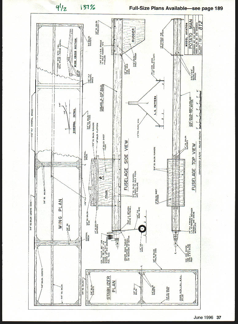
Plans / Diagrams
- Wing plan
- Dihedral detail
- Wing cross section
- Stabilizer plan
- Fuselage side view
- Pylon
- Landing gear pattern
- Rudder
- Fuselage top view
Transcribed from original scans by AI. Minor OCR errors may remain.

