
Prime Cut
Dick Sarpolus
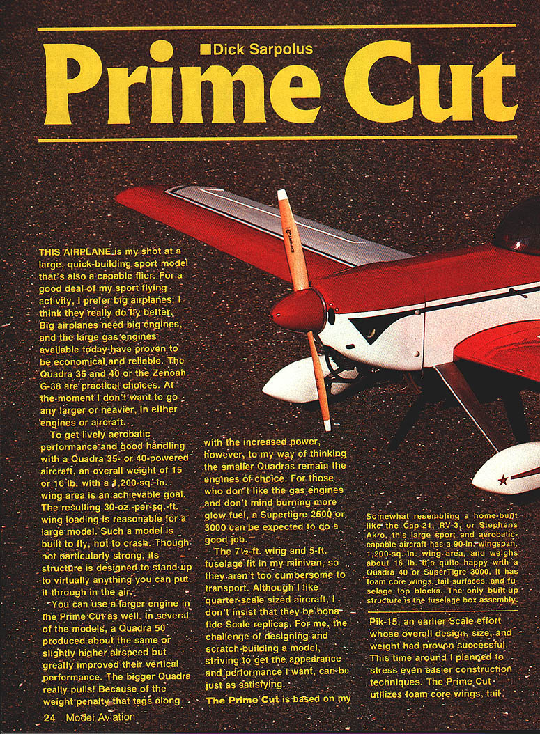
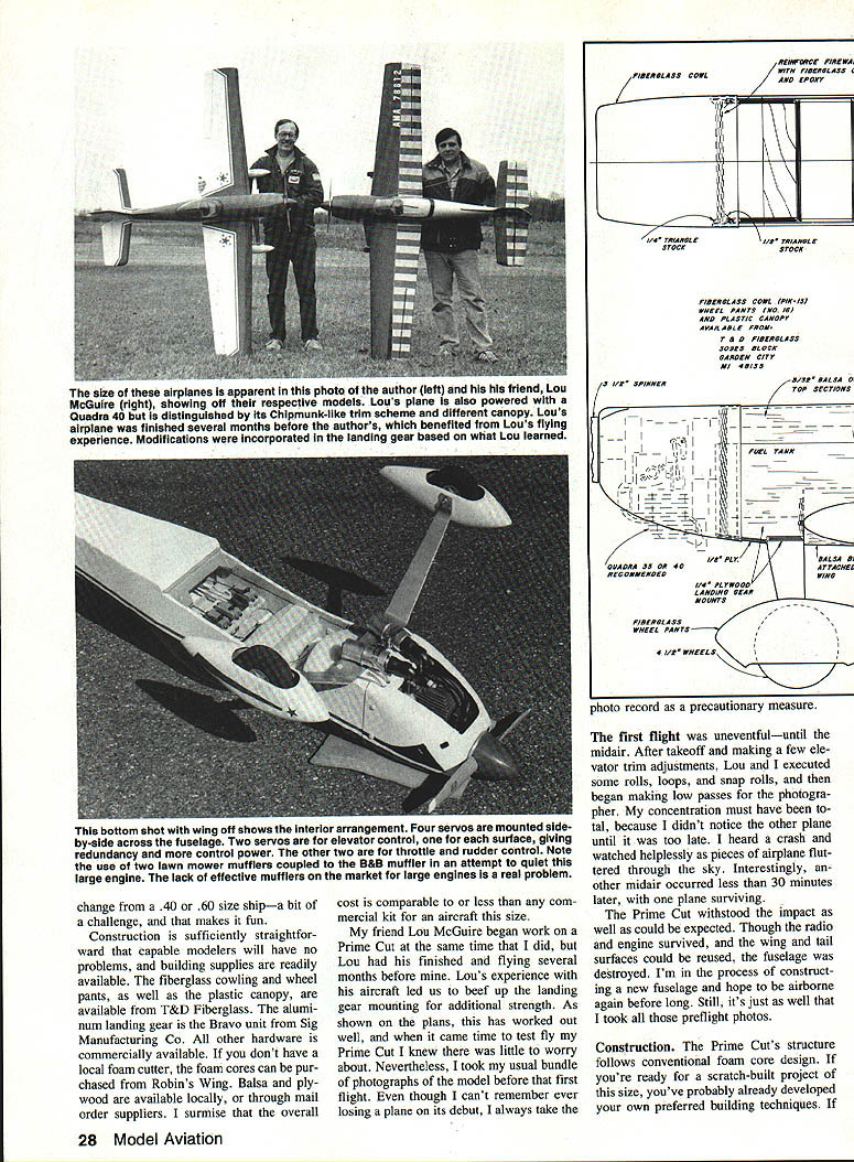
This airplane is my attempt at a large, quick-building sport model that's also a capable flier. I prefer big airplanes — I think they really do fly better. Big airplanes need big engines, and the large gas engines available today have proven to be economical and reliable. The Quadra 35 and 40 or the Zenoah G-38 are practical choices. You can also use a Quadra 50 for improved vertical performance, or a SuperTiger 2500/3000 if you prefer glow power and don't mind higher fuel consumption.
To get lively aerobatic performance and good handling with a Quadra 35- or 40-powered aircraft, an overall weight of 15–16 lb with about 1,200 sq in of wing area is an achievable goal. The resulting wing loading (about 30 oz per sq ft) is reasonable for a large model. The Prime Cut is built to fly, not to crash: the structure is not overly heavy but is designed to stand up to virtually anything you can put it through in the air.
The 7-1/2 ft wing and 5 ft fuselage fit in my minivan, so transport isn't a problem. I like quarter-scale-sized aircraft but don't insist on strict scale replication. The Prime Cut is scalelike without replicating any particular design — derived primarily from the Pik-15 with touches of the Cap, Laser, Chipmunk, RV-3, and Akro. It melds proven aerodynamic parameters with very easy construction techniques.
Design and Specifications
- Wing area: ≈ 1,200 sq in
- Span: 90 in (7.5 ft)
- Root chord: 16 in
- Tip chord: 10.5 in
- Aspect ratio: 6.8:1
- Airfoil: fully symmetrical; thickness ≈ 16.8% at root, 17.8% at tip (full aerobatic capability)
- Horizontal stabilizer area: 250 sq in (≈21% of wing area)
- Fuselage length: 62 in (provides adequate tail moment for stability)
- Typical engines: Quadra 35, Quadra 40, Quadra 50, Zenoah G-38; SuperTiger 2500/3000 (glow) also suitable
Control and configuration notes:
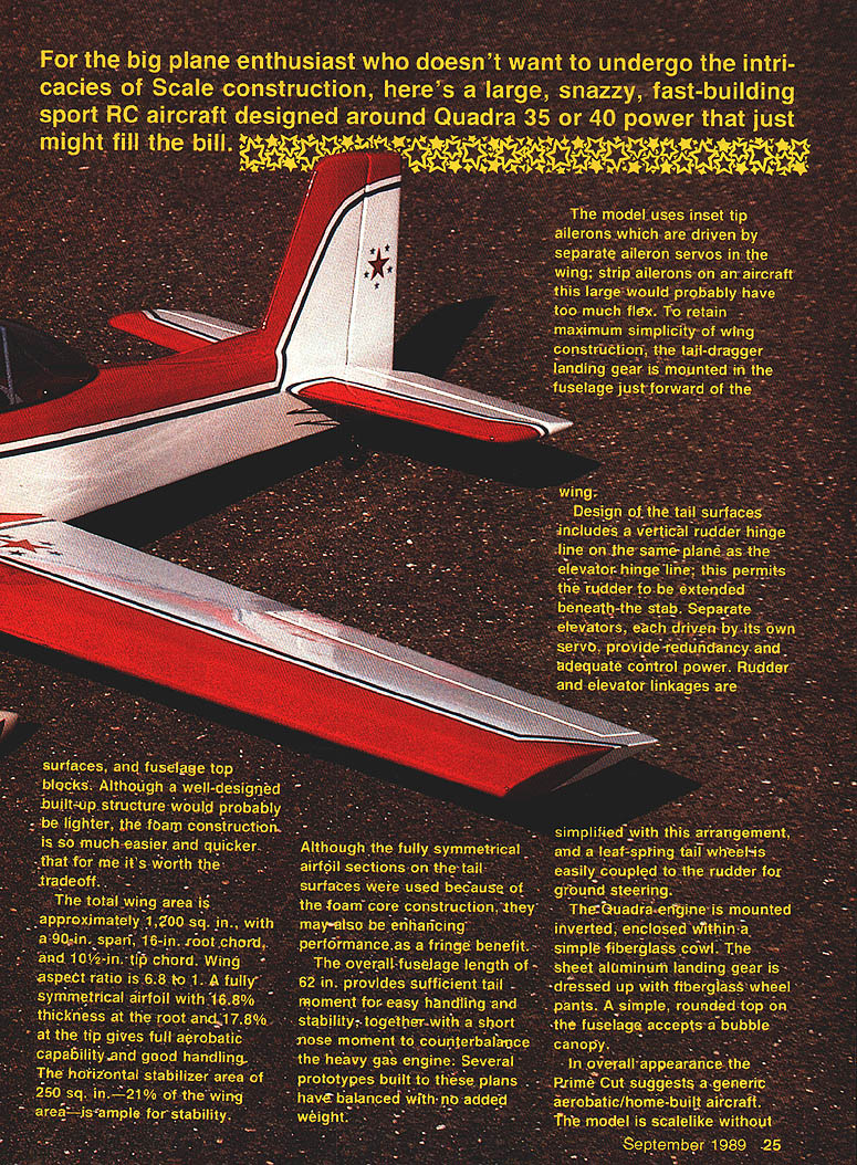
- Inset tip ailerons driven by separate servos mounted in the wing (strip ailerons would be too flexible on an aircraft this large).
- Taildragger landing gear mounted in the fuselage just forward of the wing for simple wing construction.
- Vertical rudder hinge line is in the same plane as the elevator hinge line so the rudder can extend beneath the stabilizer.
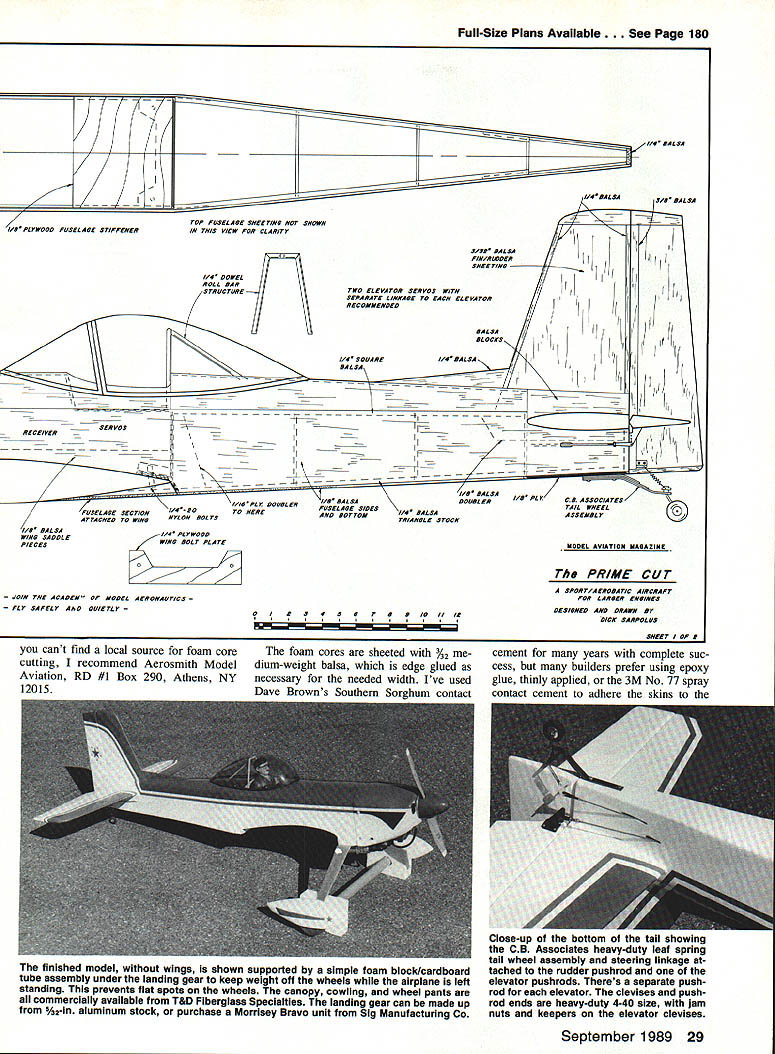
- Separate left and right elevators, each driven by its own servo, provide redundancy and good control power.
- Leaf-spring tailwheel coupled to the rudder for ground steering.
- Quadra is mounted inverted and enclosed in a simple fiberglass cowl; landing gear finished with fiberglass wheel pants.
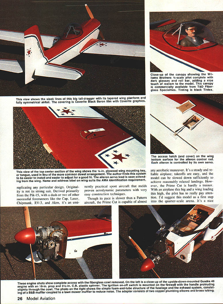
- Bubble canopy and rounded fuselage top for appearance; roll bar and pilot figure add realism.
Performance and Handling
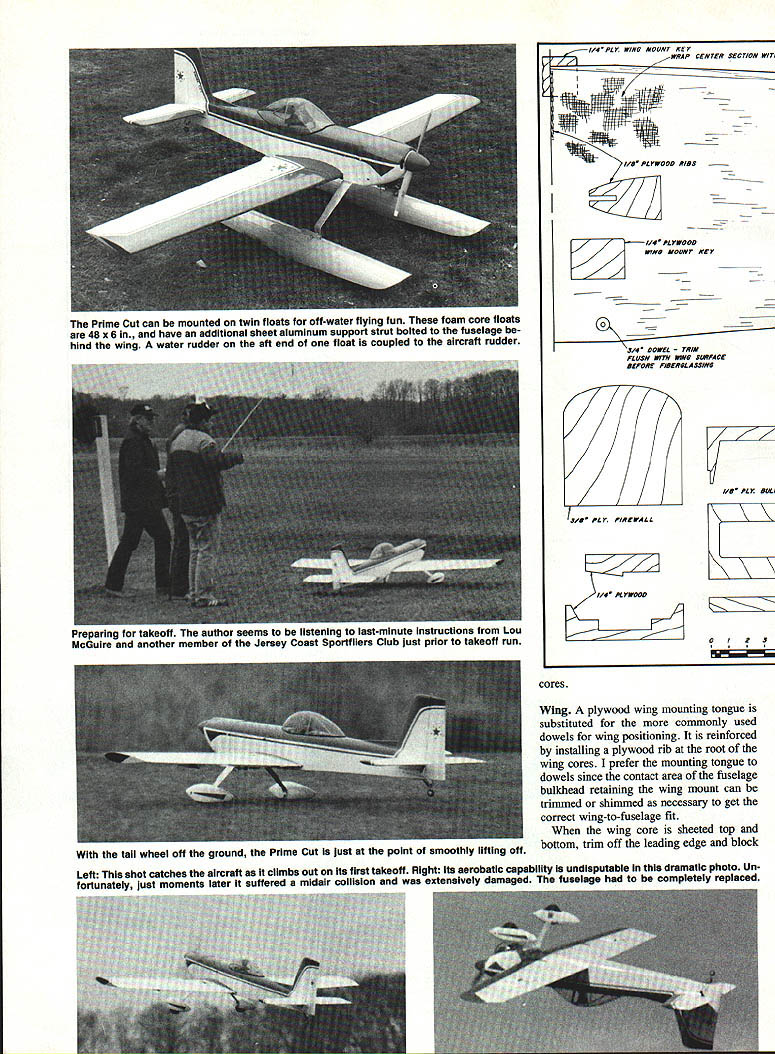
The Prime Cut suggests a generic aerobatic/home-built aircraft. It is not as fast as a Pattern ship but is capable of almost any aerobatic maneuver. Takeoffs are easy; the model can be slowed to permit relaxed landings. It is not a trainer — with a large airframe and higher wing loading the pilot must pay attention. I recommend it as a first step into quarter-scale aircraft for pilots with some experience.
Flying tips:
- Trim for hands-off flight at about 1/4 throttle; it will glide nicely when power is reduced.
- Takeoffs: apply full throttle and let it fly off the ground.
- Landings: use some power on approach and reduce to idle just before touchdown. Bleed off speed and add a bit of power if it seems to drop.
- Do not attempt high-alpha or aggressive snap maneuvers until thoroughly familiar with the model.
- A smoke system is a nice option; treat large props (18 in) with respect. Always have a helper when starting and running up the engine.
Test Flight Incident
On the first flights we had an unfortunate midair collision while making low photo passes. Pieces fluttered down; one plane survived, the other lost its fuselage. Fortunately the radio and engine survived and the wing and tail surfaces could be reused. I rebuilt the fuselage and returned to flying. Take photos before first flights — they can be useful.
Materials and Suppliers
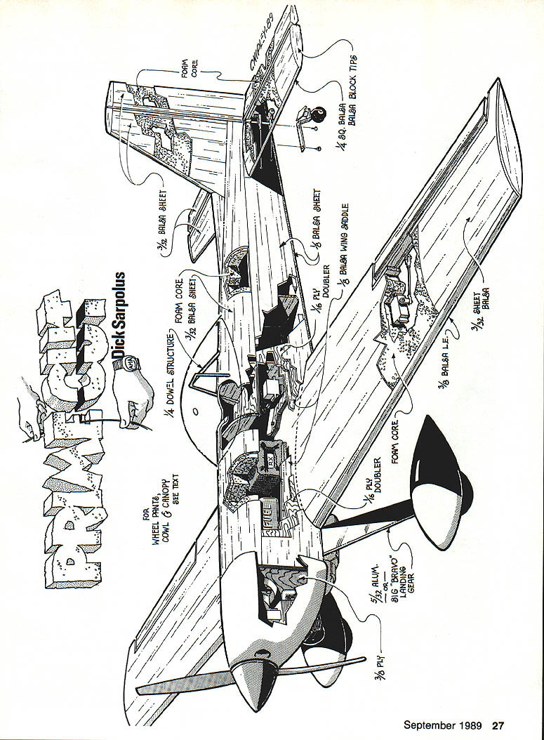
- Foam core sheeting (foam cores sheeted with 3/32 in medium-weight balsa)
- 3/32 in balsa sheet for skins and edges
- 1/8 in plywood doublers (servo mounts, etc.)
- 3/32 in balsa wing saddle pieces
- 1/4 in dowel/structure for roll bar, etc.
- 3/8 in plywood (firewall)
- 1/4 in plywood wing bolt plate and reinforcements
- Fiberglass cowl and wheel pants (T&D Fiberglass)
- Morrissey Bravo landing gear (Sig Manufacturing Co.) or sheet-aluminum gear cut from 1/8 in stock
- Robins Wing or local foam cutters for foam cores (if you cannot cut locally)
- C.B. Associates leaf-spring tailwheel assembly
- B&B muffler and aftermarket muffler ideas (see muffler section)
If you need a foam-cutter source, Aerosmith Model Aviation (RD #1 Box 290, Athens, NY 12015) is recommended. Robins Wing will supply foam cores. Balsa and plywood are available through local hobby shops or mail-order suppliers.
Construction
The Prime Cut follows conventional foam-core design. Foam cores are sheeted with 3/32 in balsa, edge-glued as necessary for width. I use contact cement (Dave Brown's Southern Sorghum) successfully; others use epoxy thinly applied or 3M No. 77 spray contact cement.
Wing
- Reinforce the wing root with a plywood mounting tongue (preferred over dowels) and a plywood rib at the root for a good wing-to-fuselage fit. The tongue allows trimming/shimming the contact area for alignment.
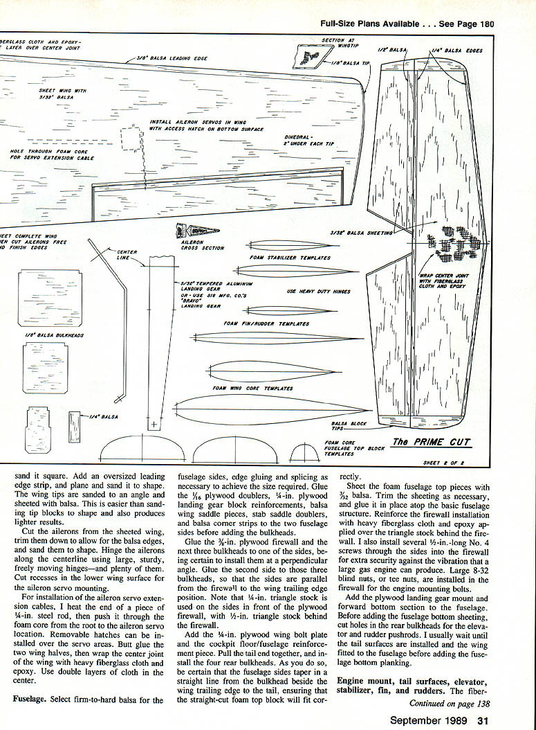
- After sheeting top and bottom, trim off the leading edge and block-sand to contour. Add an oversized leading-edge strip, plane and sand to shape.
- Tip construction: sand wing tips to angle and sheet with balsa for lighter, easier tips than carved blocks.
- Cut ailerons from the sheeted wing; allow for balsa edges and sand to shape. Hinge along the centerline with large, sturdy, freely moving hinges — use plenty of them.
- Cut recesses in the lower wing surface for aileron servo mounting.
- For aileron servo cable routing, heat the end of a 1/4 in steel rod and push it through the foam core from root to servo location to make a conduit. Install removable hatches over servo areas.
- Butt-glue wing halves, then wrap the center joint with heavy fiberglass cloth and epoxy. Use double layers in the center.
Fuselage
- Use firm-to-hard balsa for fuselage sides, edge-glue and splice as needed. Glue 1/8 in plywood doublers, 1/4 in plywood landing gear block reinforcements, balsa wing saddle pieces, stab saddle doublers and balsa corner strips to the fuselage sides before adding bulkheads.
- Glue the 3/8 in plywood firewall and the next three bulkheads to one side, ensuring they are perpendicular. Glue the second side to those bulkheads so the sides are parallel from firewall to wing trailing-edge. Use 1/4 in triangle stock in front of the firewall and 1/2 in triangle stock behind it.
- Install the 1/4 in plywood wing bolt plate and cockpit floor/fuselage reinforcement. Pull the tail together and install the four rear bulkheads; ensure fuselage sides taper straight from the bulkhead beside the wing trailing edge to the tail so the foam top block fits.
- Sheet the foam fuselage top pieces with 3/32 in balsa, trim as needed and glue in place. Reinforce the firewall area with heavy fiberglass cloth and epoxy over the triangle stock behind the firewall.
- Install several 1/2 in No. 4 screws through the sides into the firewall for extra vibration security. Use 8-32 blind nuts or tee nuts in the firewall for engine mounting bolts.
- Add the plywood landing gear mount and forward bottom section. Before bottom sheeting, cut holes in rear bulkheads for elevator and rudder pushrods. I usually wait until tail surfaces are installed and the wing fitted before adding bottom planking.
Engine Mount, Cowl, Tail Surfaces
- Trim the fiberglass cowl to clear the engine cylinder. Mount the cowl with four nylon bolts into tapped holes in the fuselage sides. Tap holes in 1/4 in plywood for the aluminum landing gear (held with 1/4 in nylon bolts).
- Sheet tail-surface foam cores with 3/32 in balsa. Cut sheeting apart along hinge lines and trim back for balsa edging. Join horizontal stabilizer halves and reinforce joint with fiberglass cloth and epoxy; glue stabilizer into fuselage.
- Each elevator is driven by its own servo and pushrod. Glue the vertical fin in place; rudder linkage via pushrod or cables. Tailwheel steering linked to rudder by small springs. Shape and install balsa blocks behind the fuselage to support the receiver, battery and other radio components.
- Recess control surfaces to accept 1/4 in plywood mounting pieces for nylon horns; retain horns with self-tapping sheet-metal screws and epoxy the plywood mounts into the control surfaces. Use 4-40 threaded rods and clevises for linkages. Fiberglass pushrods are used for elevator linkages.
Linkages and Radio Installation
- Use separate servos for left and right elevators and run straight pushrods for each; because pushrods cross in the fuselage, rotate one elevator servo 90° to prevent the pushrods from rubbing.
- Aileron extension cables can be combined into a Y-harness for the two wing aileron servos.
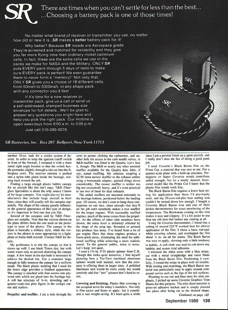
- A 1,200 mAh battery pack wrapped in foam rubber fits in a recess cut into the foam fuselage top block. It can be located behind the wing post if needed for balance.
- Mount the ignition cutoff switch forward of the firewall using a sheet-metal right-angle bracket so the handle protrudes through a small slot in the cowl. Route the receiver antenna into a nylon tube glued inside the fuselage, run it back toward the tail.
Landing Gear, Tailwheel, Canopy
- Landing gear: sheet-aluminum gear cut from 1/8 in stock or use the Morrissey Bravo gear from Sig. Secure fiberglass wheel pants by inserting screws through the aluminum gear into a plywood block epoxied inside the wheel pants. Sig and B&B Specialties make cast-aluminum pants and brackets.
- Tailwheel: use the heavy-duty leaf-spring tailwheel model from C.B. Associates.
- Fuel: I used a 16-oz fuel tank; space is available for a larger tank or another 16-oz tank for a smoke system. Route fuel lines out the bottom of the fuselage and move the muffler away from the fuselage to prevent heat damage to the foam.
- Canopy: large bubble canopies are hard to find; T&D Fiberglass Specialties carries several. Kit manufacturers that produce large aircraft may sell canopies separately. The canopy shape affects appearance strongly, so choose carefully. Tinting the canopy with black Tintex dye in warm (not hot) water provides a good look — fully immerse for a uniform tint. Attach canopy with four screws into plywood tabs glued into the fuselage top. A 1/4 in dowel roll bar and a quarter-scale pilot figure enhance realism.
Propeller and Muffler
- I cut cowl holes for choking the carb and for access to needle valves. A B&B muffler was fitted to the Quadra, but available mufflers do little actual muffling for large engines. I coupled inexpensive lawn-mower mufflers to the exhaust outlets with homemade adapters; this quieted things considerably. Two mower mufflers can be used for dual exhausts.
- Mount added mufflers externally on the fuselage bottom below the landing gear. Be sure to keep mufflers away from foam and fuel lines.
- Noise also comes from the propeller; rounded or pointed prop tips produce less noise. Many club members report lower-pitch engines that need less additional muffling.
Covering and Finish
- I used Coverite's Black Baron film for covering the foam-cored, sheeted model. Black Baron requires a lower heat setting than heavier films; a Coverite Black Baron iron and pocket thermometer are handy. A setting around 225°F worked well for overall application. Overlap seams by about 1/8 in. Apply with care to compound curves; a soft cloth can be used to work out bubbles.
- Trim stripe and star graphics can be cut from the Black Baron film or use Coverite Graphics Trim Sheets. Coverite also sells die-cut star packs in multiple sizes (red and blue stars used on my model) for easier trim.
- Coverite offers Black Baron epoxy paint in matching colors (including spray cans) — a good choice for fiberglass cowl and wheel pants.
- Although I put a painted finish on a sport aircraft, I did not miss the paint-job fun — Black Baron makes a neat, quick finish.
Miscellaneous Tips
- Reinforce the landing-gear mounting; my friend Lou McGuire and I beefed up the gear mounts based on his early flying experience, and the modification worked well.
- Use heavy fiberglass cloth and epoxy at the wing center joint and firewall areas.
- Use screws and blind nuts or tee nuts in high-vibration areas (engine mounts).
- Keep fuel lines and mufflers clear of foam and heat sources.
- If you don't have a local foam cutter, you can buy foam cores; foam cores simplify and speed construction even though a built-up structure might be lighter.
Suppliers and Sources
- T&D Fiberglass — cowlings, wheel pants, plastic canopies (large canopies)
- Sig Manufacturing Co. — Morrissey Bravo landing gear, other hardware
- Robins Wing — foam cores (if you cannot cut locally)
- Aerosmith Model Aviation — recommended foam-cutting source (RD #1 Box 290, Athens, NY 12015)
- B&B Specialties — mufflers; cast-aluminum wheel pants and brackets
- C.B. Associates — leaf-spring tailwheel assemblies
- Coverite — Black Baron film, trim sheets, matching epoxy paints
Final Notes
The Prime Cut is a steady, predictable, and responsive large sport flier. It requires careful piloting but rewards with aerobatic capability and attractive appearance. Construction is straightforward for capable builders, and supplies are readily available. The overall cost should be comparable to or less than a commercial kit of this size. Treat the big model and its large prop with respect; safe flying is essential.
Transcribed from original scans by AI. Minor OCR errors may remain.

