
A Primer on Aerodynamics
By Harold deBolt
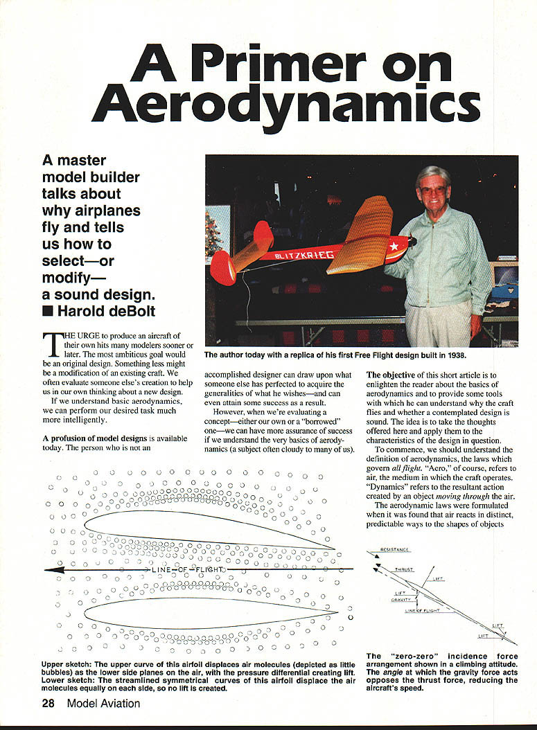
A master model builder talks about why airplanes fly and tells us how to select—or modify—a sound design.
The urge to produce an aircraft of one’s own hits many modelers sooner or later. The most ambitious goal is an original design; something less might be a modification of an existing craft. We often evaluate someone else’s creation to help us in our own thinking about a new design.
If we understand basic aerodynamics, we can perform our desired task much more intelligently. This short article is intended to enlighten the reader about the basics of aerodynamics and to provide tools to understand why a craft flies and whether a contemplated design is sound. Take these thoughts and apply them to the characteristics of the design in question.
Definition and fundamentals
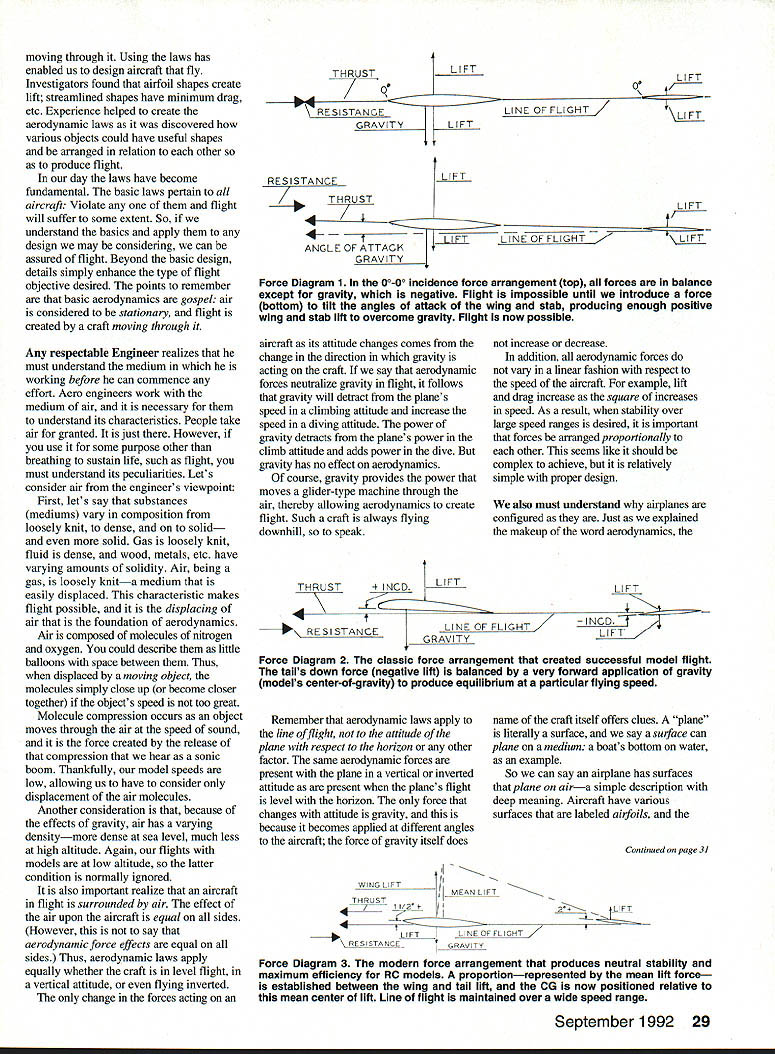
“Aero” refers to air, the medium in which the craft operates. “Dynamics” refers to the resultant action created by an object moving through the air. Aerodynamic laws were formulated when it was found that air reacts in distinct, predictable ways to the shapes of objects. Using those laws we have designed aircraft that fly: investigators found airfoil shapes create lift, streamlined shapes minimize drag, and so on.
These basic laws pertain to all aircraft. Violate them and flight will suffer. If we understand the basics and apply them to any design we consider, we can be more assured of success. Beyond the basic design, details simply enhance the type of flight objective desired.
Two points to remember:
- Air is considered to be stationary and flight is created by a craft moving through it.
- Aerodynamic forces are determined by the interaction between the craft’s surfaces and the surrounding air.
The medium: air (an engineer’s viewpoint)
Any respectable engineer knows he must understand the medium in which he works. Air, being a gas, is a loosely knit medium that is easily displaced. This characteristic makes flight possible; displacing air is the foundation of aerodynamics.
Key properties of air:
- Composition: mainly nitrogen and oxygen molecules, which can be thought of as little balloons with space between them.
- Displacement and compression: at model speeds we consider only displacement of molecules. At very high speeds (approaching sound) compression occurs and release of that compression produces a sonic boom.
- Density variation: gravity causes air density to vary with altitude—more dense at sea level, less dense at altitude. Model flights are usually at low altitude, so this effect is normally ignored.
An aircraft in flight is surrounded by air; the effect of the air upon the aircraft exists on all sides. Aerodynamic laws therefore apply whether the craft is in level flight, vertical attitudes, or inverted. The only change when attitude changes comes from the change in the direction gravity acts on the craft. Gravity itself does not change aerodynamics, but it adds or detracts from forward speed in climbs and dives, and it provides the energy that moves gliders through the air.
Aerodynamic forces do not vary linearly with speed. For example, lift and drag increase with the square of speed, so when stability is required over a wide speed range, forces must be proportioned relative to one another.
Surfaces and stability
Consider the name “airplane.” A “plane” is literally a surface, and an airplane has surfaces that plane on air. The term airfoil applies to the entire lifting surface: wing, rudder, stabilizer, canard, etc. Each surface is used because it produces a force needed to create and maintain flight. If a surface does not produce a useful force, it has no aerodynamic value.
Surfaces in the horizontal plane are called wings. In a normal monoplane configuration there are two primary wings: the main forward surface and the aft stabilizing wing (stabilizer).
Any unrestrained airfoil surface is not inherently stable. If you drop a loose surface with its chord parallel to the ground, it will tend to rotate about a spanwise axis as it falls. If a wing is the main support of flight, another force must restrain it at a useful angle of attack. The simplest way to accomplish this is with a second, aft wing (the stabilizer) which affects the forward wing’s tendency to rotate and locks it into the desired angle of attack.
In flight, all surfaces—main wing and stabilizing surfaces—generate desirable forces. The question is how those forces are applied: do they add to the efficiency of flight or simply stabilize some other surface?
Force arrangements
“Force arrangements” are diagrams that depict how all forces act upon a contemplated aircraft design. They show forces relative to the line of flight (the design reference). With models, we commonly assume the thrust line is also the line of flight (the datum line), and we refer incidence angles, centers of drag, and other measures to that datum.
A few practical notes about thrust and force lines:
- If thrust is offset from the line of flight, the aircraft tends to fly along a compromise line between thrust direction and aerodynamic forces.
- Move the thrust line away from the center of resistance (the point where total drag is assumed to act) and you introduce a pitching moment: thrust above the center of resistance causes a nose-down moment; thrust below it causes a nose-up moment.
- When the thrust line is angled relative to the flight line, some fuselage surfaces are no longer parallel to flight and drag increases.
With those basics, we can examine three common force arrangements used in model aircraft design.
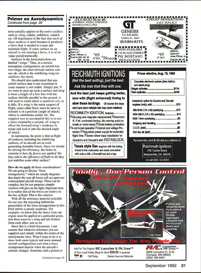
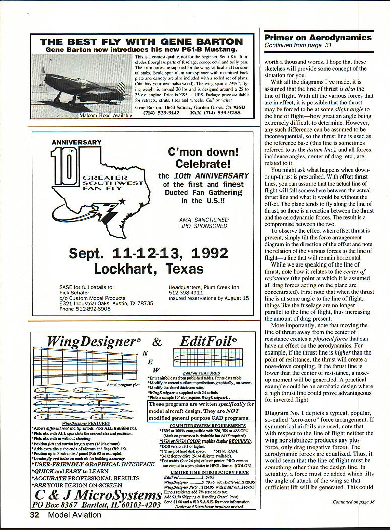
Diagram No. 1 — “Zero-zero” arrangement
This popular arrangement assumes symmetrical airfoils set at zero incidence relative to the line of flight. With respect to the line of flight, neither wing nor stabilizer produces net lift—only drag. To sustain level flight, some force must tilt the wing and tail into lifting angles. This can be accomplished by:
- Using thrust/resistance interactions to tilt the effective incidence, or
- Choosing a semi-symmetrical or cambered wing section that produces positive lift at the same incidence.
If the wing has a semi-symmetrical airfoil set at zero incidence it will produce lift; the stabilizer (if symmetrical) at zero will produce no lift and will be driven away from zero incidence until equilibrium is reached. In reality the design line of flight will deviate to the attitude where forces balance.
Diagram No. 2 — Traditional Free Flight arrangement
This is the arrangement that got many free-flight (FF) models airborne. The thrust line and line of flight are the same. The wing is set at a positive lifting angle while the stabilizer produces negative lift. Equilibrium is achieved by placing the center of gravity (CG) far enough forward of the wing’s center of lift (C/L) so the weight balances the tail’s negative lift. The longitudinal pivot point for moments is the wing’s C/L.
Characteristics:
- This is a “constant speed” arrangement: the stabilizer is adjusted to produce enough negative lift at a desired flying speed to balance the nose-down moment created by a forward CG.
- In FF, the desired flight sequence is climb with power on, then a glide with power off. The trick is to use just enough power to climb without stalling or looping as speed changes.
- This arrangement can be safe: if speed increases, the balance often causes the nose to rise instead of pitching down, offering a forgiving response for trainers.
Diagram No. 3 — Neutral stability (NS)
Diagram No. 3 shows an arrangement that provides neutral stability: the ability of the model to fly at any desired attitude over a wide speed range with no inherent nose-up or nose-down tendency. It is often said a neutrally stable model “goes where you point it.”
Key points:
- Both wing and tail produce positive lift. The mean center of lift (resultant of wing and stabilizer) lies aft of the wing’s C/L.
- The CG must be located relative to this mean lift point, not simply the wing’s C/L.
- There are moment arms from the wing C/L and tail C/L to the mean point. The tail’s moment arm is usually much longer (roughly 12 times), allowing the tail to be much smaller while exerting the required stabilizing moment.
- Over the desired speed range, if the stabilizer responds proportionally to the wing as speed changes, the model remains balanced. If the pilot commands an attitude change with elevator, the model will maintain the new attitude without an inherent tendency to return to the previous one.
- Gravity is constant; changes in power change speed and therefore lift. In an ideal NS design, increasing power raises altitude like an elevator without a nose-up pitch, and reducing power lowers altitude without a nose-down pitch.
Practical considerations:
- NS gives a solid, “on-rails” feel many pilots enjoy. However, there is no self-recovery built in: you must maintain control at all times.
- Designing for NS might seem complex, but experience shows that normal-size stabilizers with respectable symmetrical airfoils and adjustable incidence are usually adequate. Once a successful relationship between wing and tail is found, it often holds across a variety of designs.
Explaining the force diagram (summary)
- In the NS case both wing and tail lift are positive and combine to a resultant mean lift point used for CG positioning.
- The tail is often set at a greater angle than the wing to achieve the proper lift balance without an oversize tail; this is normal and effective.
- In the “zero-zero” case, an external force (thrust/resistance or a cambered wing) is needed to create a positive wing incidence for lift.
- In the traditional FF case, a forward CG and negative tail lift balance wing lift to achieve equilibrium at the desired speed.
Conclusion
This discussion has hardly exhausted aerodynamics, but applying these basic considerations will give you much more assurance in design and evaluation. Understand the medium in which your model operates, make a force arrangement diagram showing expected forces and moments, and compare force arrangements from proven designs to unknown ones. The force arrangement of a proven design makes an excellent comparison for a design that’s untested.
Once you have some experience with these fundamental ideas you’ll find it simple to delve deeper, eventually gaining an understanding that can lead you to design your own plane.
Part II: “The Aerodynamic Primer—Trimmer” will discuss how to apply these factors to improve your model trimming. Good luck!
Transcribed from original scans by AI. Minor OCR errors may remain.

