
Product Review
Frank Granelli 24 Old Middletown Rd., Rockaway NJ 07866
Four Pi OT-40
Pros:
- Many preformed parts make building fun.
- Outstanding flying qualities.
Cons:
- The instruction booklet could be more complete.
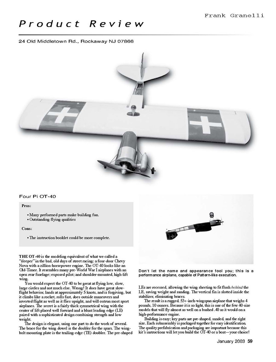
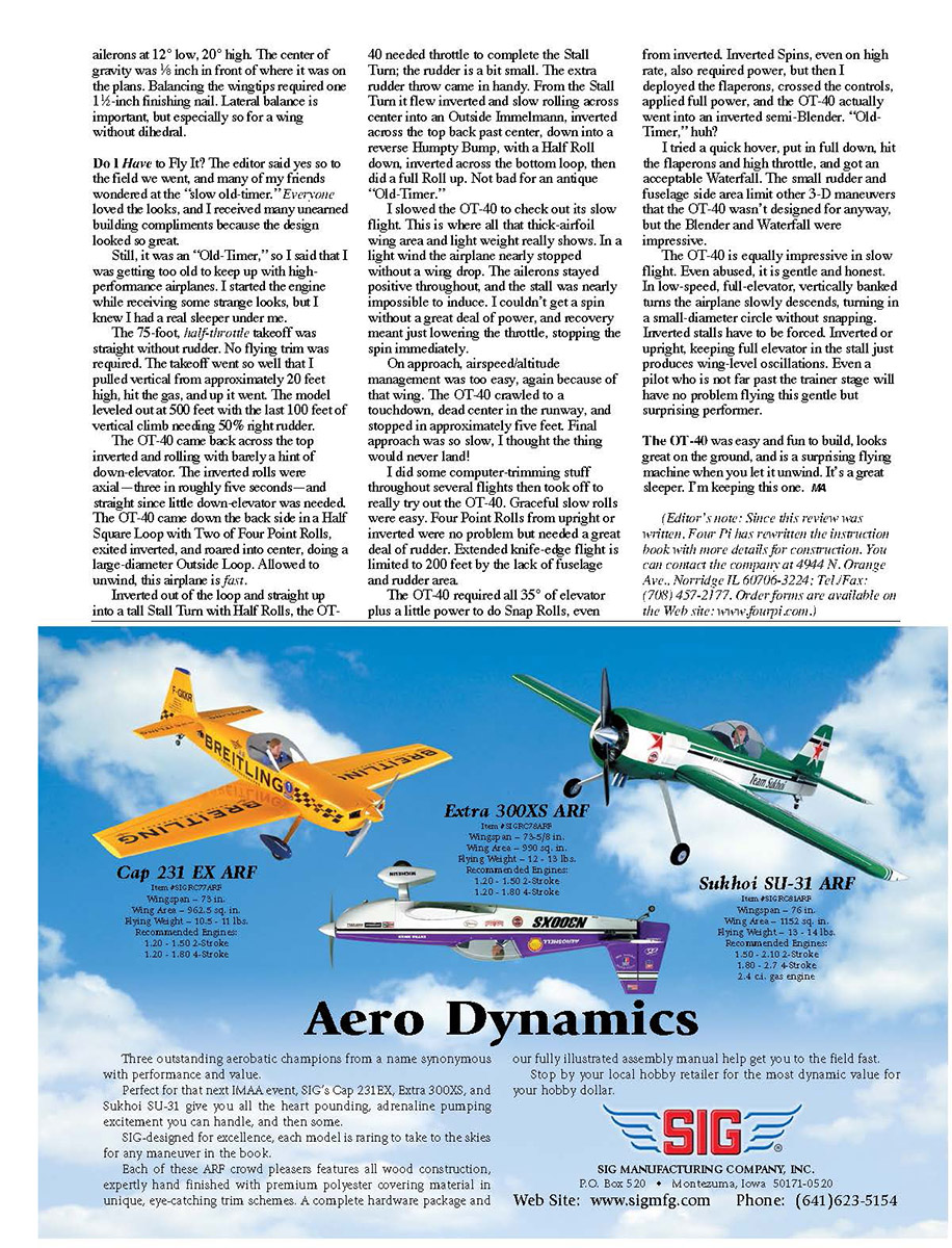
Overview The OT-40 is the modeling equivalent of a "sleeper": an Old-Timer appearance with surprisingly high performance. It resembles many pre–World War I airplanes with an open rear fuselage, exposed pilot, and a shoulder-mounted, high-lift wing. You would expect it to fly slow, make large circles, and little else. Wrong. The OT-40 has excellent slow-flight behavior and lands at roughly 5 knots, but it also climbs like a rocket, rolls fast, performs outside maneuvers and inverted flight as well as upright, and will outrun most sport airplanes.
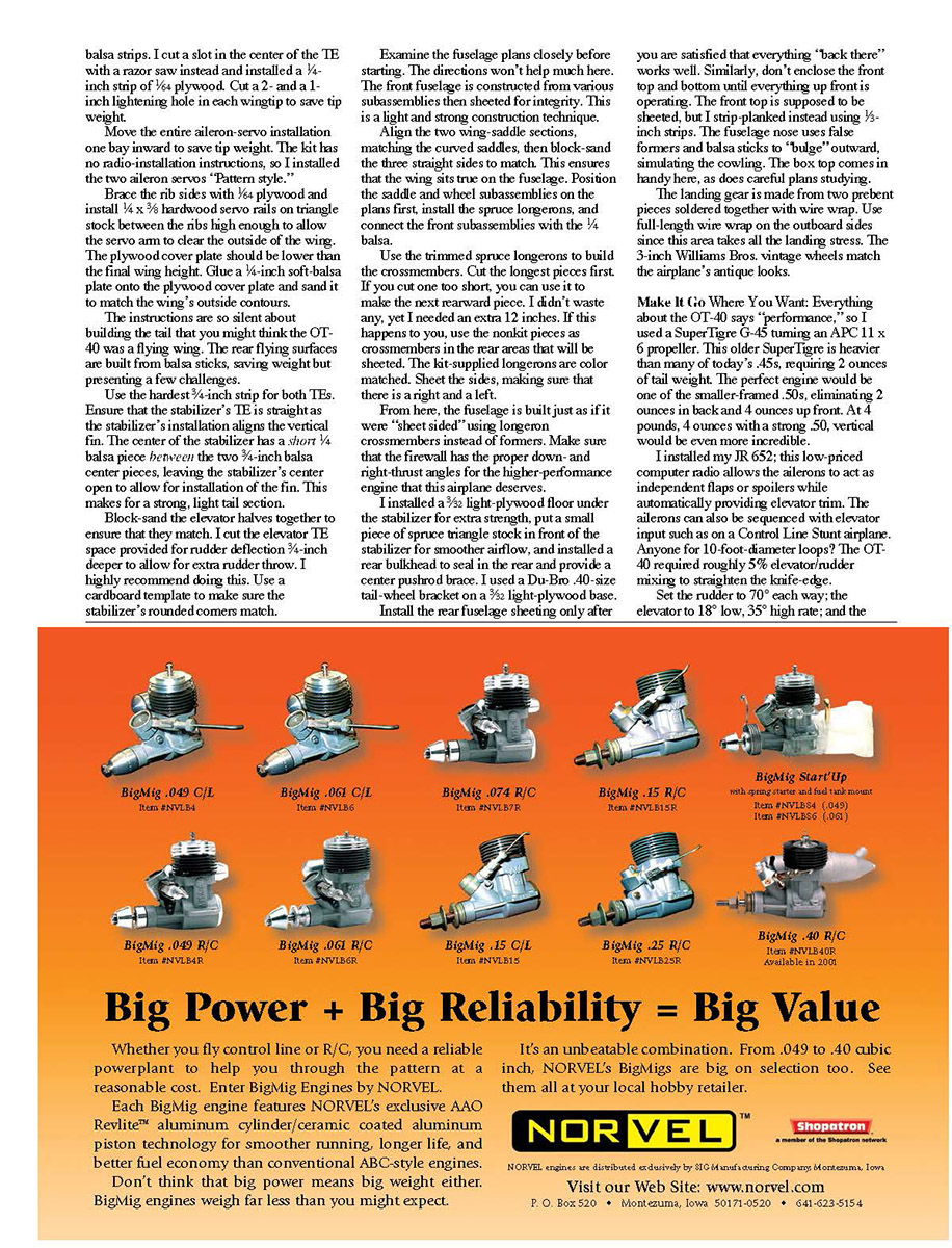
The secret is a fairly thick symmetrical wing with the center of lift placed well forward and a blunt leading edge paired with a design that combines strength and low weight. The design is elegant and efficient: one part often does the work of several. Examples: the brace for the wing dowel is the doubler for the spars; the wing-bolt mounting plate is the trailing-edge doubler; pre-shaped leading edges are recessed so wing sheeting fits flush; and the vertical fin is slotted inside the stabilizer, eliminating braces. The result is a rugged airplane with a 53+-inch wingspan that weighs 4 lb 10 oz. Because it is so light, the OT-40 will fly almost as well on a bushed .40 as it would on a high-performance engine.
Construction
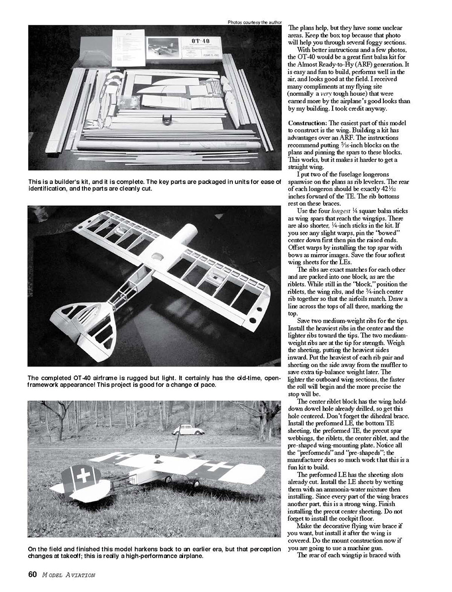
Building is easy because key parts are pre-shaped, sanded, and properly sized. Each subassembly is packaged together for easy identification; the manufacturer's prefabrication and packaging are important because the kit's instructions are sparse in places.
Wing
- The wing is the easiest subassembly. The instructions recommend using 5/16-inch blocks and pinning spars to them, but I found it easier to place two fuselage longerons spanwise on the plans as rib levelers. The rear of each longeron should be exactly 42 1/32 inches forward of the trailing edge; rib bottoms rest on these braces.
- Use the four longest 1/4-inch square balsa sticks as wing spars reaching the wingtips. If you see slight warps, pin the bowed center down first and the raised ends, or offset warps by installing the top spar with bows as mirror images.
- Save the four softest wing sheets for the leading edges. Ribs are matched and packed together; while still in the block, position the riblets, wing ribs, and the 3/4-inch center rib so the airfoils match and draw a line across the tops to mark orientation. Use the heaviest ribs in the center and lighter ribs toward the tips; save two medium-weight ribs for the tips for strength.
- Weigh the sheeting and place the heaviest sides inward. Put the heaviest of each rib pair and sheeting on the side away from the muffler to save extra tip-balance weight later. Lighter outboard wing sections yield faster roll initiation and crisper stops.
- The center riblet block has the wing hold-down dowel hole predrilled—get this centered. Don't forget the dihedral brace.
- Install the preformed leading edge, bottom trailing-edge sheeting, preformed trailing edge, precut spar webbings, riblets, center riblet, and the pre-shaped wing-mounting plate. The preformed leading edge has sheeting slots already cut; wet the LE sheets with an ammonia-water mixture before installing.
- Finish installing the precut center sheeting and do not forget the cockpit floor.
- Decorative flying-wire braces may be made but install them after covering. If mounting a machine gun, do mount construction now.
- I braced each wingtip rear with balsa strips; instead, I cut a slot in the center of the TE and installed a 1/4-inch strip of 1/64 plywood, and cut 2- and 1-inch lightening holes in each wingtip to save weight.
Radio and servo installation
- Move the entire aileron-servo installation one bay inward to save tip weight. The kit includes no radio-installation instructions; I installed the two aileron servos "pattern style."
- Brace rib sides with 1/64 plywood and install 1/4 x 3/8 hardwood servo rails on triangle stock between the ribs, high enough to allow the servo arm to clear the outside of the wing. The plywood cover plate should be lower than the final wing height. Glue a 1/4-inch soft-balsa plate onto the plywood cover plate and sand to match the wing contour.
Tail
- The instructions are silent about tail construction; the rear flying surfaces are built from balsa sticks, saving weight but requiring care.
- Use the largest 3/4-inch strip for both trailing edges. Ensure the stabilizer TE is straight because the stabilizer installation aligns the vertical fin.
- The stabilizer center has a short 1/4-inch balsa piece between the two 3/4-inch center pieces, leaving the center open for fin installation. This yields a strong, light tail section.
- Block-sand elevator halves together to match. Increase the elevator TE space provided for rudder deflection by 3/4 inch to allow extra rudder throw—highly recommended. Use a cardboard template to match stabilizer rounded corners.
Fuselage
- Study the fuselage plans closely—the directions offer little help. The front fuselage is constructed from subassemblies then sheeted for integrity, a light-and-strong technique.
- Align the two wing-saddle sections, match the curved saddles, and block-sand the three strut sides to match so the wing sits true on the fuselage. Position the saddle and wheel subassemblies on the plans first, install the spruce longerons, and connect the front subassemblies with 1/4-inch balsa.
- Use trimmed spruce longerons to build crossmembers; cut the longest pieces first. If you cut one too short, use it for the next rearward piece. If you need extra, use nonkit pieces as rear crossmembers in areas to be sheeted. Kit-supplied longerons are color matched—sheet the sides, making sure there is a right and left.
- From here, build the fuselage as if sheet-sided using longeron crossmembers instead of formers. Make sure the firewall has the proper down- and right-thrust angles for a higher-performance engine.
- I installed a 3/32-inch light-plywood floor under the stabilizer for extra strength, added a small spruce triangle in front of the stabilizer for smoother airflow, and installed a rear bulkhead to seal the rear and provide a center pushrod brace. I used a Du-Bro .40-size tail-wheel bracket on a 3/32-inch light-plywood base.
- Install rear fuselage sheeting only after confirming rear components work well. Do not enclose the front top and bottom until front components operate. The front top is supposed to be sheeted, but I strip-planked it with 1/8-inch strips. The fuselage nose uses false formers and balsa sticks to bulge outward and simulate the cowl.
Landing gear
- The landing gear is two prebent pieces soldered together with wire wrap; use full-length wire wrap on the outboard sides since these take landing stress. The 3-inch Williams Bros. vintage wheels match the airplane's antique looks.
Make It "Go Where You Want"
Everything about the OT-40 says performance, so I used a SuperTigre G-45 turning an APC 11 x 6 propeller. This (or similar) is heavier than many of today's .45s, requiring 2 ounces of tail weight. The ideal engine would be one of the smaller-framed .50s, eliminating 2 ounces in back and 4 ounces up front. At 4 lb 4 oz with a strong .50, vertical performance would be even more incredible.
I installed a JR 652 computer radio; this low-priced unit allows the ailerons to act as independent flaps or spoilers while automatically providing elevator trim. Ailerons can also be sequenced with elevator input like a control-line stunt airplane. The OT-40 required roughly 5% elevator/rudder mixing to straighten the knife-edge.
Recommended control throws and setup:
- Rudder: 70° each way.
- Elevator: 18° low rate, 35° high rate.
- Ailerons: 12° low, 20° high.
- Center of gravity: about 1/8 inch forward of the plans location.
- Balancing the wingtips required one 1-1/2-inch finishing nail. Lateral balance is important, especially for a wing without dihedral.
Flight Impressions (Do I Have to Fly It?)
The editor said yes, so to the field we went. Spectators admired the looks and I received many compliments. I started the engine to some strange looks—but it was a sleeper.
- Takeoff: Half-throttle takeoff was straight without rudder and no flying trim was required. I pulled vertical from roughly 20 feet, then the model leveled at 500 feet; the last 100 feet of vertical climb needed about 50% right rudder.
- Aerobatics: The OT-40 performed inverted rolls, outside loops, half square loops with two- or four-point rolls, and large-diameter outside loops with ease. Inverted rolls were axial and completed in roughly five seconds with little down-elevator needed. Stall turns needed throttle to complete because the rudder is a bit small; extra rudder throw was useful.
- Slow flight and stalls: The thick airfoil and light weight shine here. In light wind the airplane nearly stopped with no wing drop; ailerons stayed effective and stalls were hard to induce. Spins were difficult to enter without a lot of power, and recovery was immediate by cutting throttle.
- Landing: Approach speed and altitude management were very easy. The OT-40 crawled to a touchdown, centered on the runway, and stopped in about five feet.
- 3-D and harsh maneuvers: Extended knife-edge is limited by fuselage and rudder area; snap rolls needed full (35°) elevator plus power even from inverted. Inverted spins also needed power, but with flaperons deployed, crossed controls, and full power the OT-40 went into an inverted semi-blender. A quick hover with full down, flaperons, and high throttle produced an acceptable waterfall. The small rudder and side area limit other 3-D maneuvers, but Blender and Waterfall were impressive.
- Handling: The OT-40 is gentle and honest even when abused. In low-speed, full-elevator, vertically banked turns it slowly descends and turns in a small circle without snapping. Inverted stalls must be forced; holding full elevator produces wing-level oscillations rather than violent departures. A pilot slightly beyond trainer level will handle it easily.
Conclusion
The OT-40 is easy and fun to build, attractive on the ground, and a surprising performer in the air. It's an excellent sleeper—an antique look with modern performance. I'm keeping this one. MA
Editor’s note: Since this review was written, Four Pi has revised the instruction book with more construction detail. Contact Four Pi at 4949 N. Orange Ave., Norridge IL 60706-3224. Tel/Fax: (708) 457-2177. Order forms are available on the website: www.fourpi.com.
Transcribed from original scans by AI. Minor OCR errors may remain.

