
Professional Cut
Dick Sarpolus
Enlarging an RC Pattern design to suit a larger engine is nothing new. When a two-stroke .60 was the standard engine, modelers enlarged Pattern designs for the new .90-size engines. When larger gas/ignition engines appeared, a few builders enlarged Pattern designs to suit the big powerplants. As gas engines grew in popularity and larger glow engines were introduced, most modelers went for large scale aircraft and a smaller number of large sport designs. When moving up to Giant Scale size, Caps, Lasers, and Extras were built for their aerobatic fun.
RC Pattern designs developed into the highly specialized aircraft used in competition today—forms that do not at all resemble full-scale aerobatic types. During several discussions on sport aircraft design for larger engines, Dean Pappas suggested I try today’s Pattern aerodynamics in the larger size I prefer. I had been out of Pattern competition flying for a long time and was wary of the very long fuselage, long tail moment, highly tapered wing, etc., of Pattern types. Dean felt those characteristics would result in a good-flying large-size model, even with gas/ignition power.
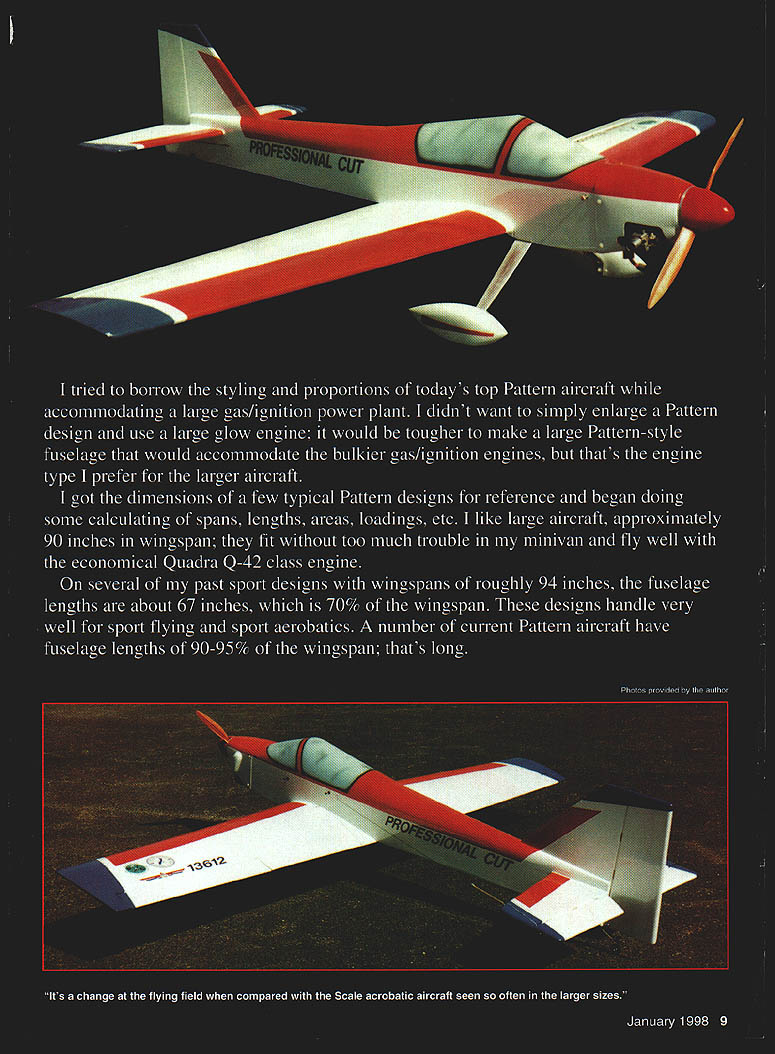
I tried to borrow the styling and proportions of today's top Pattern aircraft while accommodating a large gas/ignition powerplant. I didn’t want to simply enlarge a Pattern design for a large glow engine; it would be tougher to make a large Pattern-style fuselage that would accommodate the bulkier gas/ignition engines, but that is the engine type I prefer for the larger aircraft.
I collected dimensions from a few typical Pattern designs for reference and calculated spans, lengths, areas, loadings, etc. I like large aircraft, approximately 90 inches in wingspan; they fit without too much trouble in my minivan and fly well with the economical Quadra Q-42 class engine. On several of my past sport designs with wingspans of roughly 94 inches, the fuselage lengths are about 67 inches, which is 70% of the wingspan. Those designs handle very well for sport flying and sport aerobatics. A number of current Pattern aircraft have fuselage lengths of 90–95% of the wingspan; that’s long.
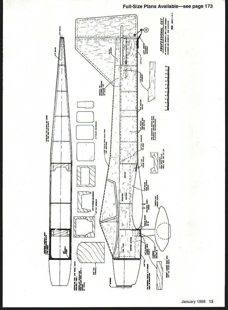
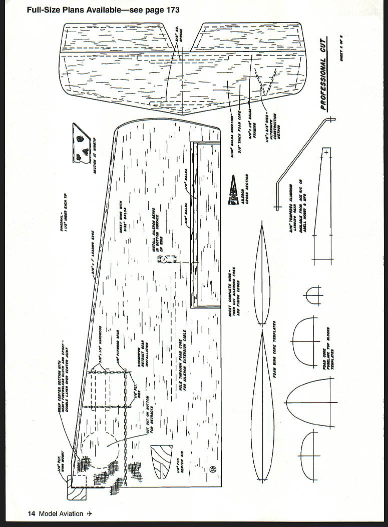
I laid out a 90-inch-span wing with a straight trailing edge and fairly high taper; it had about 1,400 square inches of area. I drew up a Pattern-type fuselage that seemed very long at 80 inches in length—almost 90% of the wingspan. That was long enough for me to try. With those parameters I worked up the rest of the Professional Cut layout.
Dean tells me the very latest Pattern designs are “square” or even oversquare—the fuselage is as long or longer than the wingspan. I could have gone even longer, but as it is now the airplane barely fits in the back of my minivan.
The Pro Cut fuselage was made just wide enough for the Sachs, and with the forward canopy styling it’s still fairly sleek for that Pattern look. The fin and rudder are larger than I'm used to, but are in proportion to the long fuselage and Pattern layout. The wing has the Pattern outline and a fairly thick symmetrical airfoil that provides easy handling.
The plans show a retract-gear taildragger setup and a standard sheet-aluminum fixed landing gear; my prototype aircraft has the sheet-aluminum gear mounted on the fuselage with wheel pants. Fixed gear bolted to the fuselage is very easy and quick and works well. The airplane would look really sleek with retracts up, but that would mean more work, weight, and expense—your choice.
Tricycle gear, either fixed or retractable, would probably be a bad choice: the model would be heavier, and it’s hard to get a really strong, rugged nose gear for an airplane of this size and weight.
Fiberglass cowl and wheel pants are available from Fiberglass Specialties (51200 Milano Dr., Suite A, Macomb, MI 48042). I’ve used the same items before on other designs. Steve Durecki’s fiberglass parts are light, adequately strong, and easy to finish.
With the styling and layout completed, I went with a very conventional, basic, and easy building structure: balsa-sheeted foam wing cores, a basic box fuselage with balsa sides and plywood doublers, foam-cored fuselage top blocks sheeted with balsa, and foam-cored tail surfaces. The one-piece wing bolts in place beneath the fuselage rather than using plug-in wing panels. It’s lighter and easier to build, and the wing just fits in my minivan.
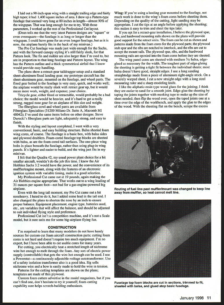
I felt the Quadra Q-42, my usual powerplant choice for a bit smaller aircraft, wouldn't do the job this time. I knew the Air Hobbies Sachs 3.2 would have the power and the convenience of its muffler/engine mount, along with the features of an electronic ignition system with variable timing, making it a good selection.
My Professional Cut came out at 19 pounds, making the Air Hobbies engine appropriate. That works out to a wing loading of about 31 ounces per square foot—not bad for a gas-engine-powered big airplane. Even with the long tail moment, the Pro Cut came out a bit nose-heavy. I hated to do it, but I added some lead in the tail and also changed the plans to shorten the nose by 1 inch to ensure proper balance. Equipment placement, engine type, batteries used, and so on are variables that will affect the balance and should be adjusted to suit individual flying style and preference.
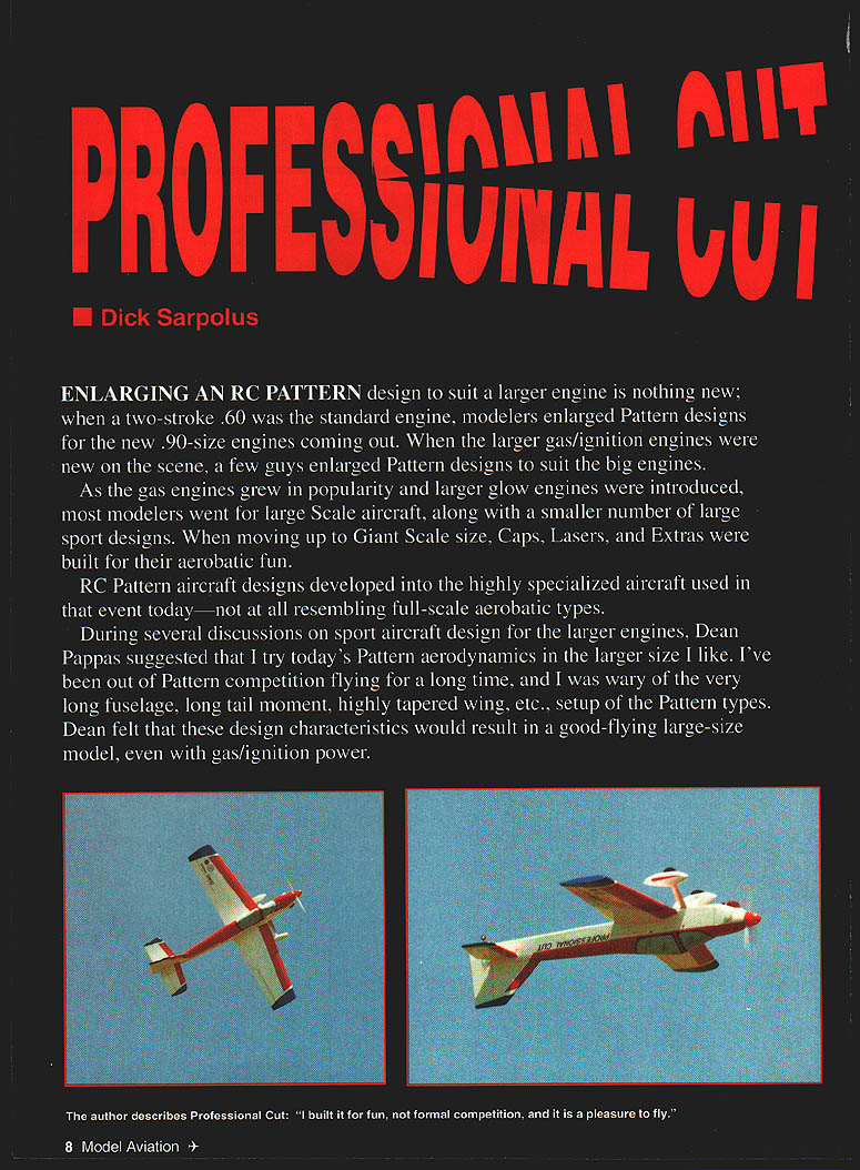
Professional Cut isn't a competition machine and it's not a scale replica, but it suits me for some big-airplane flying fun.
Construction
I'm surprised to learn many modelers do not have handy sources for custom-cut foam aircraft parts. Cutting foam cores is not hard and doesn't require much equipment. I’m no expert, but I have been able to cut usable cores for many years.
For cutting, electrically heat a stretched length of nichrome wire hot enough to melt through the foam. Any controllable electric power supply that gets the wire hot enough can be used. I use a Powerstat—a continuously adjustable-voltage autotransformer. Use of a safety-isolation transformer is also a good idea. SIG sells nichrome wire and a bow is easily made to hold the wire in tension. Patterns for the cutting templates are shown on the plans; templates are made of thin plywood.
Custom foam cutters advertise in the model magazines, but if you can’t find one, don’t hesitate to try it yourself. Foam-cutting capability helps scratch-building enthusiasts.
Wing
If the landing gear is mounted to the fuselage (fixed gear), not much work is done to the wing's foam cores before sheeting them. Depending on the quality of the cutting, light sanding may be appropriate. I cut the tips at an angle before applying the sheeting; this makes it easy to trim and sheet the tips later.
If you opt for a retract-gear installation, the plywood spar, ribs, and hardwood mounting rails shown on the plans will provide good support for the retract units. The foam can be cut as shown and patterns made from the foam cores for the plywood parts; the plywood stub spar and the ribs are notched to interlock, and the ribs are cut to accept the mounts. Epoxy the plywood spar, ribs, and hardwood mounting rails into the foam cores before sheeting.
The wing panel cores are sheeted with medium 3/32" balsa, edge-glued as necessary for the width. The toughest part of edge-gluing the sheeting is getting a tight fit between individual sheets; most balsa doesn’t have good, straight edges. I use a long sanding straightedge made from a piece of aluminum right-angle stock. On a severely warped sheet, cut a new straight edge with a long steel measuring ruler and a sharp modeling knife.
I like aliphatic-resin wood glues for joining; I think they are easier to sand for a smooth joint. Edge-glue the sheeting by taping the joints together with masking tape to make up the size of sheet needed, then flip the wood over, open the taped joints, and set the panels onto the edge joint on one of the tops of the workbench. Apply glue to the edges, scrape excess glue off each joint with a putty knife, and weight the wood until the glue dries. Remove the masking tape; the taped side becomes the outer surface of the sheeting.
Sand the inside surface of the sheeting with rough sandpaper to speed the work, and use fine sandpaper to finish off the outer surface. I strongly recommend Dave Brown's Southern Sorghum contact cement to apply the wing sheeting; I have used it for years. Alternatives are thinly applied epoxy, some spray-can cements, or whatever you prefer—just be sure it works for you.
With the core sheeted top and bottom, trim off the leading edge and block-sand it square. Add an oversized balsa leading-edge strip and plane and sand it to shape. Cut and sand the sheeting to match the cutoff tip angle, and add the tip sheeting; round the edges slightly.
Cut the ailerons from the sheeted wing and trim them down to allow for the balsa edging, which is glued in place and sanded to shape. Hinge the ailerons along the centerline, using large, sturdy, freely moving hinges of the type you prefer. Keep the gap between the aileron and the wing as tight as possible while still permitting free movement. Do not glue the hinges in place now; that will be done after covering.
Recesses are cut into the lower wing surface for the aileron servo mounting. Epoxy plywood mounting pieces in position to suit your servos, having them protrude from the wing surface just enough for hookup of the aileron pushrods. A hole is needed through the foam core from the root to the location of the aileron servo for the servo extension cable. To melt a tunnel, heat the end of a 1/4" metal rod with a propane torch and push the hot end through the foam.
A plywood wing-mounting tongue is used at the leading edge to position and retain the wing. It is reinforced by a plywood rib installed at the root of the wing cores. Done this way, the contact area of the fuselage bulkhead retaining the wing mount can be trimmed or shimmed as necessary to get the correct wing-to-fuselage fit.
Sand the root ends of the wing panels to fit tightly together with the tips blocked up at the dihedral angle; I used 1 1/2" under each tip. Modelers are very opinionated about dihedral: if you believe in more or less or want the top surface of the wing flat with dihedral angle in the bottom, fine—do it your way.
Butt-glue the wing halves together, then wrap the center joint of the wing with heavy fiberglass cloth and epoxy. Use double layers of cloth in the center. I use nine-inch-wide strips of glass cloth, overlapped in the center to give a five-inch-wide double layer. Brush on a coat of epoxy, position the fiberglass cloth, and brush on additional epoxy to ensure the cloth is saturated. For a smooth appearance without too much sanding, squeegee off excess epoxy, leaving enough so the cloth is saturated for strength but smooth and level.
Fuselage
Select firm-to-hard balsa for the sides, edge-gluing and splicing as necessary to get the required size. Glue the 1/16" plywood doublers, 1/4" plywood landing-gear block doublers, balsa wing-saddle pieces, stab-saddle doublers, and balsa rear edge strips to the two fuselage sides. I like to use a 3/8" plywood firewall for mounting these large engines, laminating 1/4" and 1/8" plywood.
With one fuselage side flat on the workbench, add the firewall and the next three bulkheads, installing them perpendicular to the side. Glue the second side to those bulkheads; the sides are parallel from the firewall to the wing trailing-edge position. Add triangle stock and heavy fiberglass cloth behind the firewall to reinforce the junction with the sides. I also put several small screws into the firewall through the fuselage sides.
Add the 1/4" plywood wing-bolt plate, then pull the tail end together, installing the rear bulkheads. Be sure the fuselage sides taper in a straight line to the rear so the straight-cut foam rear top block will fit correctly. Trial-fit the block as you install the bulkheads; they can be trimmed or moved so the block fits well.
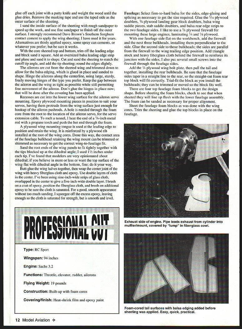
There are four top fuselage foam blocks to get the design shape. Before sheeting the foam blocks, check that when sheeting they will line up flush with the lower fuselage assembly. The foam can be sanded as necessary for proper alignment. Sheet the fuselage foam blocks as was done with the wing cores, trim the sheeting, and glue the top blocks in place on the fuselage.
Covering and Finishing
- Use heat-shrink film for covering and finish with epoxy paint if desired.
- Do not glue control surface hinges until after covering.
- For epoxy over fiberglass, squeegee excess and sand lightly for a smooth finish before painting.
Specifications
- Type: RC Sport
- Wingspan: 94 inches
- Engine: Sachs 3.2 (Air Hobbies)
- Functions: Throttle, elevator, rudder, ailerons
- Flying weight: 19 pounds
- Construction: Built-up with foam cores, balsa sheeted
- Covering/finish: Heat-shrink film and epoxy paint
Notes and Tips
- If you choose retractable landing gear, follow the plywood spar, ribs, and hardwood mounting rails detail in the plans and epoxy these parts into the foam before sheeting.
- For foam tunneling (servo runs), heat a 1/4" metal rod and push it through the foam to melt a clean tunnel.
- Edge-gluing balsa sheeting is easier if you tape joints, glue on the bench, scrape excess glue, and weight until dry.
- Use a safety-isolation transformer when building a nichrome foam cutter and consider a Powerstat for controllable heat.
- Balance will vary with equipment selection; plan for adjustments. If the model is nose-heavy, try shifting equipment first before adding ballast.
Transcribed from original scans by AI. Minor OCR errors may remain.

