
Profile AT-6
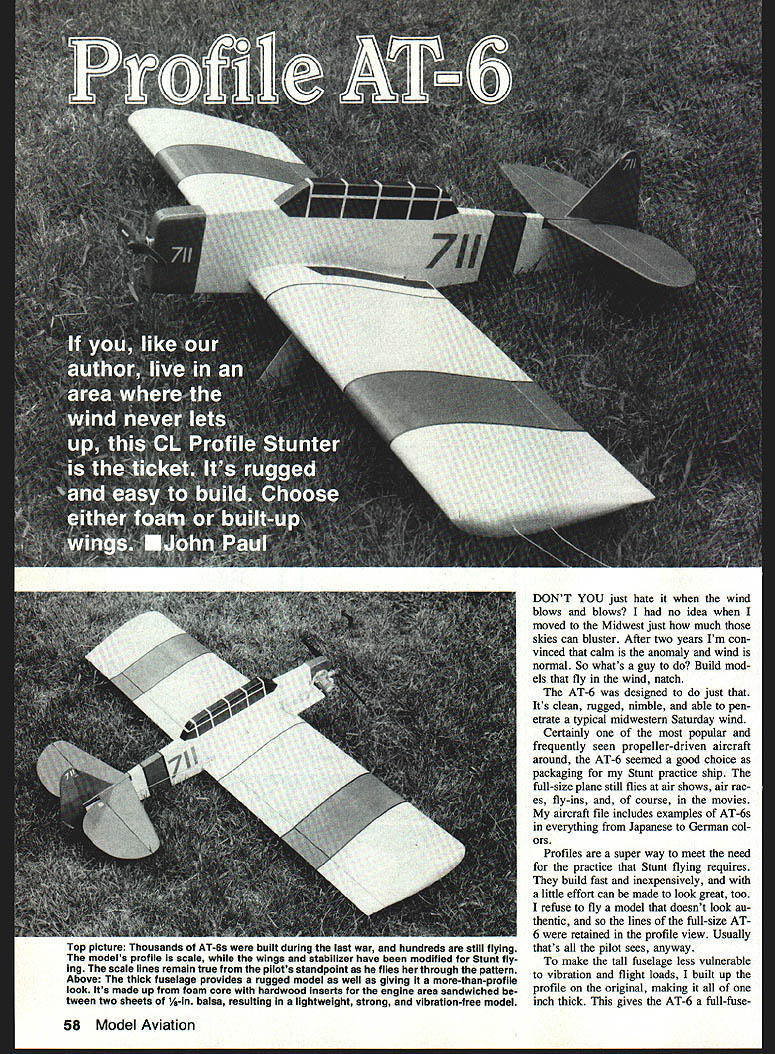
Don't you just hate it when the wind blows and blows? I had no idea when I moved to the Midwest just how much those skies can bluster. After two years I'm convinced that calm is the anomaly and wind is normal. So what's a guy to do? Build models that fly in the wind, natch.
The AT-6 was designed to do just that. It's clean, rugged, nimble, and able to penetrate a typical Midwestern Saturday wind. Certainly one of the most popular and frequently seen propeller-driven aircraft, the AT-6 seemed a good choice as packaging for my stunt-practice ship. The full-size plane still appears at air shows, air races and fly-ins — and, of course, in the movies. My aircraft file includes examples of AT-6s in everything from Japanese to German colors.
Profiles are a super way to meet the need for the practice that stunt flying requires. They build fast and inexpensively, and with a little effort can be made to look great, too. I refuse to fly a model that doesn't look authentic, so the lines of the full-size AT-6 were retained in profile view — usually that's all the pilot sees anyway.
To make the tall fuselage less vulnerable to vibration and flight loads, I built up the profile on the original, making it a full 1 inch thick. This gives the AT-6 a more-than-profile look and helps reduce vibration and structural stress.
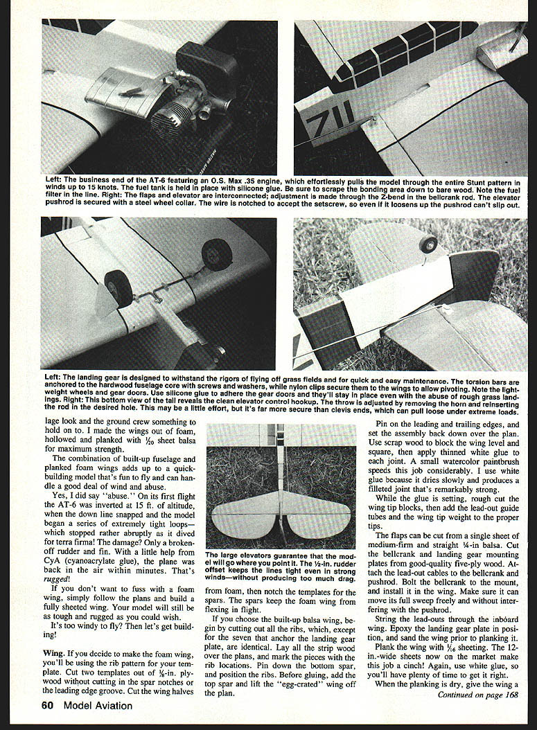
The landing gear is designed to withstand the rigors of flying off grass fields and is quick and easy to maintain. Torsion bars are anchored to the hardwood fuselage core; screws, washers and nylon clips secure the wings and allow pivoting. Note the light-weight wheels and gear doors — use silicone caulking to adhere gear doors; they'll stay in place through abuse and rough grass landings.
The tall tail reveals a clean elevator control hookup. Throw is adjusted by removing the horn and reinserting the rod in the desired hole. This may take a little effort, but it's far more secure than clevis ends, which can pull loose under extreme loads.
I made the wings out of foam, hollowed and planked with thin balsa for maximum strength and a “ground crew” look. The combination of a built-up fuselage and planked foam wings adds up to a quick-building model that's fun to fly and can handle a good deal of wind and abuse.
Yes, I did say abuse. On its first flight the AT-6 inverted at about 15 ft on the down line, snapped, began a series of extremely tight loops, stopped rather abruptly and dived to terra firma. Damage: only a broken-off rudder fin. A little CyA (cyanoacrylate) glue had the plane back in the air within minutes. That's rugged — I don't want to fuss.
If you don't want a foam wing, simply follow the plans and build the fully sheeted wing; the model will still be tough and rugged. If it's too windy to fly, let's get building.
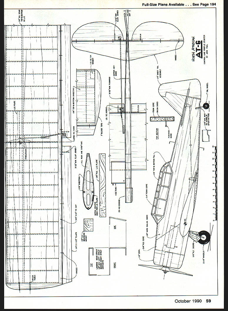
Full-size plans available. See Page 194.
Wing
If you decide to make a foam wing you'll be using the rib-pattern template. The basic steps:
- Cut two templates out of 1/8-in. plywood, cutting spar notches and the leading-edge groove.
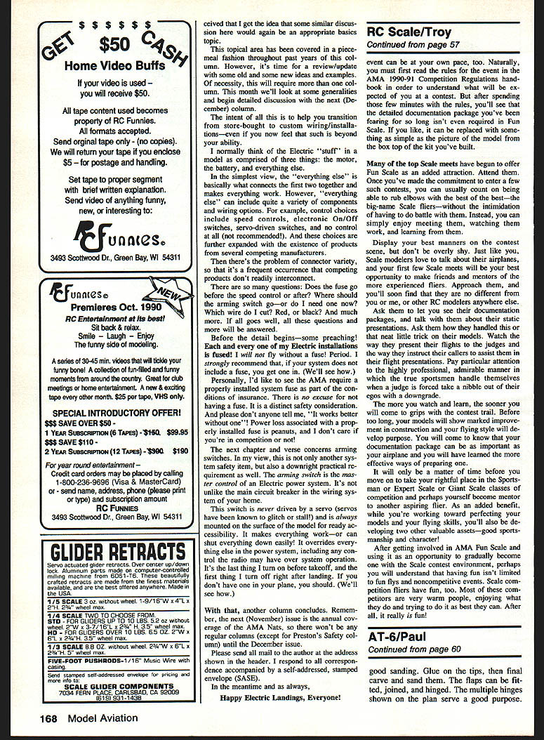
- Cut the wing halves from foam and notch the templates for spars. Spars keep the foam wing from flexing in flight.
- If making a built-up balsa wing instead, cut out all ribs (except the seven that anchor the landing-gear plate — these are identical). Lay a strip of wood over the plans and mark rib locations.
Assembly tips:
- Pin down the bottom spar and position the ribs. Before gluing, add the top spar and lift the wing slightly off the plan.
- Pin the leading and trailing edges and set the assembly back down over the plan. Use a scrap wood block to keep the wing level and square.
- Apply thinned white glue to the joints with a small watercolor paintbrush — this speeds the job considerably. White glue dries slowly and produces a filleted joint that's remarkably strong.
- While the glue is setting, rough-cut the wingtip blocks, add lead-out guide tubes and the proper wingtip weight.
- Cut the flaps from a single sheet of medium-firm, straight 1/8-in. balsa.
- Cut the bellcrank and landing-gear mounting plates from good-quality five-ply wood. Attach lead-out cables and the bellcrank pushrod.
- Bolt the bellcrank mount in place and install the wing. Ensure it can move its full sweep freely without interfering with the pushrod.
- String the lead-outs through the inboard wing. Epoxy the landing-gear plate in position and sand the wing prior to planking.
Planking options:
- For a fully sheeted wing, plank with 3/16-in. sheeting — 12-in.-wide sheets make the job easier. Use white glue for the extra working time.
- For a foam core wing planked for strength, use thin balsa sheeting (1/16-in. is typical) glued and sanded to shape.
When planking is dry, give the wing a good sanding, glue on the tips, and final carve and sand them. Fit, join and hinge the flaps. Multiple nutplates (as shown on the plan) are useful for securing gear and control fittings.
Fuselage
The fuselage is built up on the plan in the usual profile manner. Construction notes:
- The preferred structure is a foam core with hardwood inserts in the engine area sandwiched between two sheets of 1/8-in. balsa, resulting in a lightweight, strong, vibration-free model.
- Alternative method: cut the fuselage from 1/2-in. sheet balsa and proceed in the traditional way.
- Start with a 3/8-in. insulation foam blank cut to shape for the foam-core method. Cut an engine mount from 3/8-in. plywood, drill mounting holes and add blind nuts. Taper the rear of the fuselage as required.
- Sheathe both sides with 1/8-in. hard balsa; cap exposed edges with 1/8-in. sheet. Add a 1/4-in. sheet cowl to finish the nose.
- Install hardwood doublers and epoxy the landing-gear plate into position, bedding it with fillets. Fit the firewall square and mount the engine securely.
- Install tail surfaces using flat, firm balsa and round all edges before assembling. Offset the rudder only about 1/2 inch — too much offset will make the airplane mush when it slows down.
- Cut the openings in the fuselage for the wing and stabilizer; fit, square and epoxy them together. When satisfied with the fit, epoxy a lightweight fiberglass cloth strip into the wing joint to help prevent separation.
Alignment and checks:
- Make sure rudder, stabilizer, fuselage and wing are well aligned. Measure the distances from flap hinge line to elevator hinge line on each side and adjust while epoxy is still workable. Using a slower (one-hour) epoxy allows time for adjustments.
- Bend left- and right-hand landing-gear wires from 3/32-in. music wire. Fashion plywood gear doors and glue them to the wires with silicone caulking. Bend the tailwheel strut and glue it to a dowel for later assembly.
Controls, hardware and flight setup
- The elevator control uses a pushrod through the fuselage; fit the horn and check travel before final assembly. Throw is adjusted by removing the horn and reinserting the rod in the desired hole.
- Install the radio gear with easy access to the battery and receiver. Run and secure all control rods and check for free movement.
- Use clamp-on style control horns with a plate on top that secures the mounting screws. Z-bends at the horn ends and stainless steel set collars at the wire ends are recommended. Orient the wire end so the setscrew cannot slip off.
- Add a pushrod guide midway between the flap horn and the elevator horn to prevent flexing under compression loads. The guide can be bent from 7/64-in. music wire or made from a cotter key; epoxy it in position.
- Mount landing-gear struts to the wing using nylon clips and small sheet metal screws. Make certain the screws are long enough to seat well into the plywood plate. The front ends of the wires are secured by washers and screws into the plywood fuselage core.
- Install wheels, engine and propeller. Finish off the lead-out ends and balance the model at the C.G. location shown on the plan.
- For first flights, reduce control throws and trim gently until the model flies straight and true. A few washers of outthrust can help keep the AT-6 on the end of the lines.
Hinges and loads: wind and weight create tremendous loads on hinges — hinges are a lot cheaper than models, so use good hinges and inspect them regularly.
Covering and finishing
- Glue the fuel tank in place before doping the model. Silicone caulking works well for tank mounts; ensure the tank is aligned with the engine.
- Apply three coats of clear dope to the wood before covering, sanding lightly between coats.
- Cover flat areas and the wing with silkspan, doping it right to the wood to seal pores and create a resilient surface. Follow with five coats of clear dope, sanding between coats.
- Finish with a light coat or two of color dope. With millions of documented AT-6 color schemes available, choosing one can be the hardest part.
Final assembly and flying
- Install control horns and pushrods. Check travel and security of all linkages.
- Balance the model before its first test flight. A calm day is preferable, though not mandatory.
- Tune down control movements if the model proves highly responsive (short-coupled moments and ample control surfaces make the AT-6 quick to react). I fly mine with a wide-spaced handle and have found the need to reduce control throws.
- After a safe setup and test flight, let the winds blow — the AT-6 is a good trainer and fun to fly, true to her lineage.
Notes on repairs and ruggedness:
- The AT-6 survived a dramatic first-flight upset: inverted at about 15 ft, snapped, went into tight loops and dived. Damage was only a broken-off rudder fin; CyA glue returned the plane to service within minutes. That's rugged.
If it's too windy to fly, let's get building.
Transcribed from original scans by AI. Minor OCR errors may remain.

