
Profile Dauntless SBD-3
Introduction
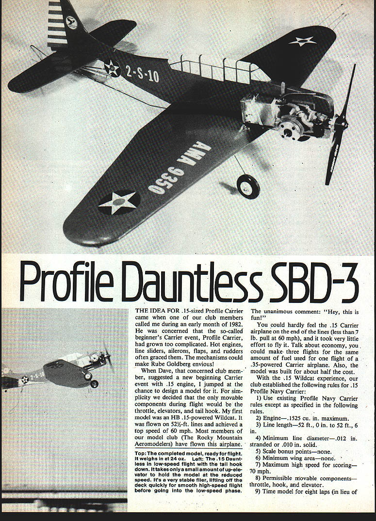
The idea for a .15-sized Profile Carrier came when a club member, Dave, called during early 1982. He felt the so-called beginner's Carrier event, Profile Carrier, had become too complicated with hot engines, line sliders, ailerons, flaps, and rudders — mechanisms that could make Rube Goldberg envious.
When Dave suggested a new beginning Carrier event limited to .15 engines, I jumped at the chance to design a simple model. We decided the only movable components in flight would be the throttle, elevators, and tail hook. My first model was an HB .15-powered Wildcat flown on 52½-ft. lines with a top speed of 60 mph. Most members of our club, the Rocky Mountain Aeromodelers, have flown that airplane.
An easy way to transfer pieces such as ribs, doublers, and spars from the plans to wood is to Xerox the component patterns, cut them out, and glue the applicable balsa and plywood pieces to them with rubber cement. After cutting, peel off the paper templates — you haven’t cut up the plans.
Rules for the new Profile Carrier model
The seven rules dictated that the next model should:
- Have wing area about 160 sq. in.
- Have a low wing — throttle control is difficult to route around the fuel tank in a mid-wing design.
- Be a replica of an actual Navy carrier airplane.
Selection: Douglas SBD-3 Dauntless
After researching World War II carrier aircraft I selected the Douglas SBD-3 Dauntless. The model span is 22½ in.; wing area is 161 sq. in.; and it has a low wing. The Douglas Dauntless was the Navy's principal carrier-based dive bomber during WWII. From Pearl Harbor until V-J Day, the airplane sank 18 warships (including six carriers) and more than 300,000 tons of enemy shipping. Dauntless gunners shot down 138 Japanese planes; fewer than 80 Dauntlesses were shot down by Japanese aircraft. At war's end it was the only U.S. carrier aircraft operational at Pearl Harbor still in service. A total of 5,321 Dauntlesses were built.
Construction overview
This model uses conventional construction techniques. The notable exceptions are the methods for mounting the landing gear and the control bellcranks. Build components in this order for best results:
- Landing gear
- Wing
- Fuselage
- Empennage (tail surfaces)
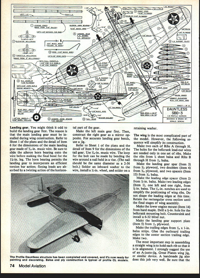
Landing gear
Build the landing gear first because the main gear must be installed during wing construction.
- Main gear: Make the main landing gear from 3/32-in. music wire (see plans Item 6). Slide the aileron horn bearing onto the wire before making the final bend for the 1-1/2-in. leg. The horn bearing permits torsion-bar action: flexing loads are absorbed by the horizontal gear twisting.
- Make the left main gear first, then make the right as a mirror image. Use a jig for accurate bends.
- Tail gear: Refer to plans Item 9. Use 5/64-in. music wire. Form the loop for the bolt by bending the wire around a nail in a vise (nail diameter equals a 2-56 bolt). Solder an inboard washer, install a 1/2-in. wheel, then solder on a retaining washer.
Wing
The wing is the most complicated part; the following sequence simplifies construction.
Materials and parts:
- Make two each of Ribs A through H. Use 3/32-in. sheet balsa for the root ribs and 1/8-in. balsa for Ribs B through H.
- Landing gear spar (Item 3): 3/32-in. plywood.
- Doublers (Item 4): two pieces of 1/16-in. plywood.
- Spacers (Item 15): two pieces of 1/8-in. balsa.
- Leading edge spacer (Item 2): 1/8-in. balsa.
- Leading edges (Item 1): two pieces, left and right, from 1/4-in. balsa (leave rectangular until final shaping).
- Lower engine mount (Item 14): hard maple; drill 1/8-in. hole for bellcrank mounting bolt and countersink for a 6-32 blind nut.
- Landing gear support plate (Item 5): 1/8-in. plywood.
- Trailing edges: 1/8 x 1-in. balsa strips.
Assembly steps:
- Use a wing jig (A-justo-jig, Great Planes wing jig, or a handmade jig) to ensure each rib chord line is the same distance above the work surface.
- Glue the lower engine mount to the root ribs. Locate and glue ribs to the trailing edges.
- Position and glue the front spar to the center-section ribs (A–D). Glue the leading edge spacer to the front spar.
- Position left and right leading edges with ribs inserted into the 1/16-in. notches; glue in place.
- Glue upper spar caps, turn the wing over, and glue the lower spar cap to the ribs. Glue leading-edge segments (Item 17) to the leading edges at the wing center section.
- Glue landing gear support plates to the front spar, ribs B and C, and the lower spar cap — these fit in notches in the spar and lie on the lower spar cap.
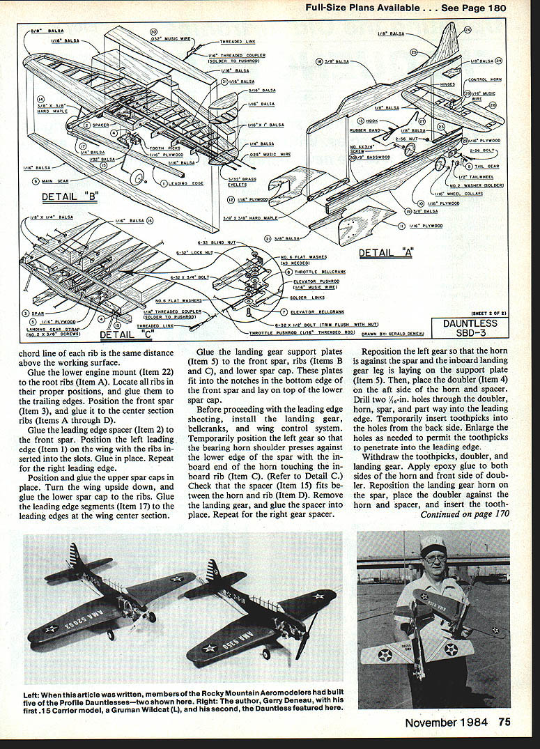
Installing the landing gear and bellcranks before sheeting:
- Temporarily position the left gear so the bearing horn shoulder presses against the lower edge of the spar with the inboard end touching rib C (see Detail C). Check that spacer (Item 15) fits between horn and rib D. Remove gear and glue spacer in place; repeat on right side.
- Reposition the left gear so the horn is against the spar and the inboard leg rests on the support plate. Place the doubler (Item 4) on the aft side of the horn and spacer. Drill two 1/16-in. holes through the doubler, horn, spar, and into the leading edge. Insert toothpicks from the back side as temporary locators.
- Withdraw the toothpicks, doubler, and gear. Apply epoxy to both sides of the horn and the front side of the doubler. Reposition the horn and doubler and insert the toothpicks; clamp until epoxy sets. Secure the landing gear leg to the support plate with the landing gear strap and No. 2 x 1/2-in. screws. Repeat for the right gear.
Bellcranks and lead-outs:
- Attach lead-out wires to the bellcranks (Detail C). Assemble the elevator bellcrank (Item 7) to the throttle bellcrank (Item B) with bolt, washers, and locknut; trim bolt flush with nut.
- Thread lead-out wires through the left wing and secure the bellcrank assembly to the lower engine mount with a bolt and washers; cut bolt flush with the top of the blind nut.
- Throttle linkage: Cut an 8-in. piece of 1/2-in. music wire, solder a clevis link to one end. Drill a 1/8-in. hole through the leading edge, leading edge spacer, and spar aligned with the outer hole of the throttle bellcrank. From inside the wing, thread the unsoldered end through the hole and engage the soldered link with the bellcrank.
- Elevator pushrod: Cut a 12-in. piece of 1/16-in. wire and solder a clevis link to one end. Drill a 1/8-in. hole through the trailing edge 3/16 in. right of the wing centerline; enlarge to a 1/4 x 3/8-in. slot. From inside the wing, slide the unsoldered end through the slot and engage the soldered link with the elevator bellcrank.
Finishing the wing:
- Glue upper and lower leading-edge sheeting to the rib leading edges and cap flanges. Glue balsa sheet segments between Ribs B–C and C–D to spar caps and ribs (Detail C, Item 16). Glue 1/4-in. sheeting to the upper and lower surfaces of the center-section ribs.
- Cut rib caps from 1/8-in. balsa and glue to upper and lower edges of ribs E, F, and G. Sand the leading edges to shape to blend smoothly into the sheeting.
- Make right wing tip from a 3/8-in. balsa block, rough shape, glue, and final-shape with sanding block.
- Make left wing tip as a sandwich: lower 1/4-in. balsa, center pieces 1/8-in. balsa, top 3/16-in. balsa (Detail B). Glue pieces, drill holes for eyelets, thread lead-out wires through, glue tip in place, sand to shape, then glue eyelets. Do not tie lead-outs to eyelets until ready to fly.
- Trailing edge: use 3/32 x 1/2-in. balsa stock; pin trailing edge to plan and glue center section, then sand to shape.
- Sheet the center section top with 1/16-in. balsa. Final-sand the wing to remove rough edges.
Fuselage
The fuselage is typical for profile models except for a basswood reinforcement strip between upper and lower fuselage pieces (Detail A).
Steps:
- Cut upper and lower fuselage pieces from 1/8-in. balsa. Cut the basswood strip (Item 20) and upper engine mount (Item 22) to length.
- Glue the basswood strip to the lower fuselage. Glue the upper engine mount to the upper fuselage, ensuring the lower surface of the engine mount is flush with the bottom surface of the upper fuselage.
- Glue the balsa spacer (Item 23) in place. Position the upper fuselage on the lower fuselage and check that a 1/4-in. slot remains for stabilizer insertion.
- Cut two round doublers (Item 10) from 1/8-in. plywood. Drill a 1/16-in. hole through each doubler and through the lower fuselage; glue doublers using a 1/16-in. wire to hold alignment (remove wire before glue sets).
- Make tail gear doublers (Item 29) from 1/8-in. plywood and glue to each side of the lower fuselage. After drying, drill a 1/16-in. hole for the front leg of the tail gear and a 1/8-in. hole for the tail gear mounting bolt.
- Redrill the 1/16-in. hole through the center of the round doublers. From the outboard side of the fuselage, drill a 1/16-in. hole 3/8-in. deep into the doubler and fuselage to locate the #6 x 3/4-in. screw.
- Sand the fuselage to final shape.
Installations:
- Install engine mount (Item 1) and fuel tank (Item 2) in the fuselage. Drill mounting holes and countersink larger holes on the firewall for blind nuts. Drill 1/2-in. mounting holes for the tank and install tank retaining wires.
- Attach the lower cowl piece and shape to fit.
Tail surfaces
- Make stabilizer (Item 27), elevators (Item 28), fin (Item 25), and rudder (Item 26) from 1/8-in. balsa. Sand to shape.
- Glue the rudder to the fin with the rudder trailing edge offset 1/2 in. Connect left and right elevators with music wire (Item 29) and secure wire to the elevators with epoxy.
- Cut slots in elevators and stabilizer for hinges. Insert hinges in the stabilizer and glue in place. After glue dries, slide elevators onto hinges and glue, taking care not to glue hinge pivots.
- Install control horn on the right elevator.
Assembly
- Slide the stabilizer and elevator assembly into the fuselage slot and secure with glue. Glue the tail cone spacer (Item 24) to the fuselage, leaving equal space between elevators and spacer.
- Glue the fin and rudder assembly to the top of the fuselage. Glue the wing to the fuselage.
- Glue the fuselage chine (Item 21) to the lower engine mount and wing leading edge. Sand joints and glue plywood reinforcements (Items 11 and 12) to the fuselage with epoxy.
- Bend the elevator pushrod to align with the elevator horn, screw and solder linkages as needed, and cut to length.
- Install the engine. Screw a threaded coupler onto a threaded link and connect to the engine throttle arm. With the arm at half-throttle and the throttle bellcrank neutral, bend the throttle pushrod to align with the coupler; cut and solder the pushrod to the coupler.
- Slide brass eyebolts over the lead-out wires and glue them into the wing tip with epoxy. Move the throttle arm to full-throttle, hold it there, and tie the ends of the lead-out wires as shown on the plans.
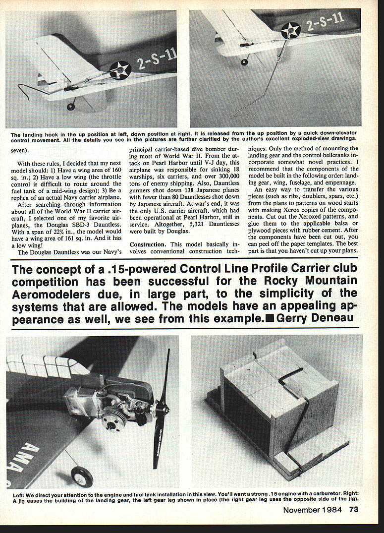
Hook installation
- Fabricate the tail hook per the plans and locate mounting holes. Install the hook so it releases up and locks down quickly when the elevator is moved. Test the hook thoroughly before flying.
- Install hook stop: insert a #6 x 1/4-in. screw into the previously drilled 1/2-in. hole until it protrudes 1/8-in.; this screw stops the hook in the down position.
- Wrap and solder a length of 1/2-in. music wire to the elevator pushrod and bend it to hold the tail hook up. Trim so the hook drops when the elevator is full down (Detail B, Item 20). Loop a rubber band around the hook and engage it with the screw extending from the round doubler. Engage the hook with the elevator pushrod and recheck that it will drop with full-down elevator.
Finishing
- Remove the engine, hook, and tail gear for finishing.
- Cover the wings and fuselage with lightweight covering (silkspan or equivalent). Dope or iron per the covering manufacturer's instructions.
- Paint: upper fuselage and upper wing surfaces blue-gray, lower surfaces light gray. Canopy windows white. Apply white fuselage lettering and star insignias (with red, white, and blue) per plan positions.
- Apply 1 oz. of stick-on lead weight to the underside of the right wing tip. Reinstall engine, tank, hook, and tail gear.
- Balance the model at the CG shown on the plan with engine and tank installed. Model should balance within ±1/4 in. of the center of gravity location shown on Sheet 1. Add nose or tail weight as needed.
Final adjustments and checks
- Check all hinges and control linkages; ensure bellcrank assemblies operate freely without binding.
- Verify the landing gear and tail hook are secure.
- Trim the model at low throttle with the elevator down to simulate carrier-deck attitude. Adjust throttle linkage so the model will fly both high- and low-speed phases without large control inputs.
Flying
- The SBD-3 Dauntless flies easily. It lifts quickly on takeoff and performs smooth high-speed flight before transitioning to low speed.
- Keep a small amount of up-elevator during the low-speed phase with the tail hook down.
- Speeds of 60–70 mph are easily attained; the author flew the Dauntless at 70 mph to take first place in a club contest.
- Slowing for low-speed flight is uneventful and requires only a small amount of up-elevator. With practice, you can get a pronounced nose-up attitude with correct throttle control.
- Landings are straightforward: pick a spot, chop throttle, and let her settle in. Three-point landings are easy.
Have fun — this .15-powered Profile Carrier Dauntless is economical to fly and looks like the real thing. Happy landings!
Transcribed from original scans by AI. Minor OCR errors may remain.

