
Profile Gee Bee R-1
Joseph M. Nunes
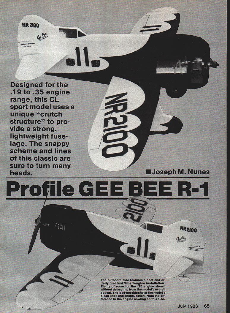
Do you get a bit excited watching Gee Bee models? During my early modeling years, when I first saw pictures of the aircraft I was immediately intrigued by its formidable shape and color appeal. "I've got to build one someday," I thought. Kit control-line projects built my interest and also turned me toward RC. Frankly, I did not want to construct a bumblebee‑like body during those earlier years, but I imagined building one once my techniques were honed.
Rereading the February 1983 issue of Model Aviation, my eyes fell upon the two‑page photo of Henry Haffke's Gee Bee R‑1 Super Sportster and I could see the possibility of satisfying a long‑held desire to construct a profile‑fuselage Gee Bee R‑1 model in the .19 to .35 engine range. The article and plan inspired a model that would be fun to build and attractive both on the ground and in the air.
The Gee Bee's use of a center crutch within the profile body allows a lighter airframe while maintaining required strength and design integrity. Construction is similar to a one‑piece profile control‑line model but well within the capability of RC modelers. The design uses a built‑up wing, lead‑out, side cowl projection, rounded fuselage edges, a built‑up rudder, non‑flat wheel pants, full tailwheel enclosure, and a snappy finish — all contributing to flying enjoyment.
Construction
Study the plan to become familiar with parts and techniques. Refer to the text and photos for additional information. You may want to assemble kit parts first before commencing full assembly. Work carefully using the plan; it will be used during finishing. Keep the model light — remove excess weight by sanding well, especially the fuselage and wing. Use both thick and thin cyanoacrylate (CyA) glue during construction except where noted. Wipe excess glue as you build. Work on a flat surface and take your time.
Fuselage
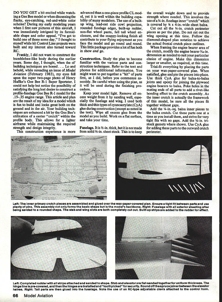
- The fuselage uses an inner crutch framework covered with sheet balsa. Follow the plan for exact crutch dimensions and outline; modify the engine bearer dimension to suit your engine.
- Cut out the crutch perimeter pieces and trial‑fit everything over wax paper on the plan. When satisfied, glue and pin pieces in place. Use thick CyA for balsa‑to‑balsa joints and epoxy for joining plywood engine bearers to balsa.
- Poke small holes in mating ends of parts for a rivet‑like bonding effect in the crutch assembly. Ensure tight fits and no gaps; add 1/8‑in. square balsa inner pieces and 1/32‑in. tin‑stock gussets where shown.
- Sand the completed inner crutch smooth so the outer skins will lay flat. Use Ambroid (or recommended adhesive) to attach the outer skins to allow sanding of glue joints without hard CyA lines. You will typically need two pieces of wide sheet stock per side to avoid multiple seams.
- Add 1/8‑in. plywood fuselage doublers at the engine area. Optionally cut lightening holes on the lead‑out side (these will be concealed by the cowl).
- Indent mating plywood/balsa surfaces with an awl for a better epoxy bond. Glue the doublers in place with epoxy and weight until cured. Remove excess epoxy.
- Trace and cut the wing cutout using the plan as a guide. Drill starter holes, then use a Dremel or similar saw to follow the outline; go slowly for a good wing‑to‑fuselage fit.
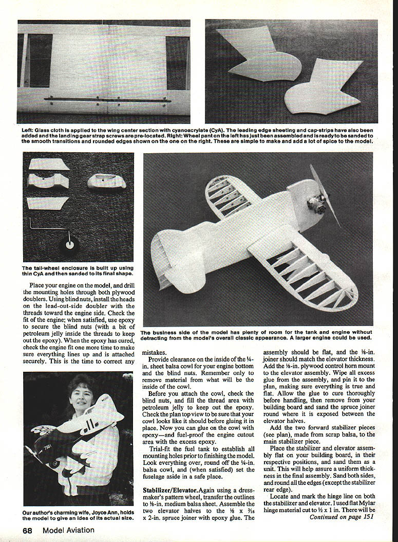
- Drill engine mounting holes through both plywood doublers, install blind nuts with threads toward the engine side, and secure with epoxy (use petroleum jelly in threads to keep epoxy out). Check the engine fit after curing.
- Provide clearance inside the cowl for engine bottoms and blind nuts. Glue the cowl in place with epoxy and fuel‑proof the engine cutout area with excess epoxy.
- Trial‑fit the fuel tank and establish all mounting holes before finishing. Round off cowl edges and set the fuselage aside once satisfied.
Stabilizer / Elevator
- Transfer outlines to 1/8‑in. medium balsa. Assemble the two elevator halves to the spruce joiner (3/32 x 3/16 x length typical) with epoxy so the assembly is flat and the joiner matches elevator thickness.
- Add the 1/8‑in. plywood control horn mount to the elevator assembly. Wipe excess glue, pin to the plan, and let cure. Round the exposed spruce joiner between elevator halves when dry.
- Add forward stabilizer pieces made from scrap balsa, then sand stabilizer and elevator as a unit for uniform thickness. Round edges except the stabilizer trailing edge.
- Locate and mark hinge lines. Pre‑cover the hinge line (MonoKote recommended), open hinge slots with a #11 hobby blade (one centered slot per hinge), apply glue, and insert flat Mylar hinges (cut to about 1/2 x 1 in). Check movement and, when satisfied, drill a small hole through balsa and hinge at each end and glue in small toothpick pieces; cut and sand flush.
- Remove the small piece of material at the stab slot (keep it). When dry, slide the stab/elevator assembly into the slot, square it to the model per plan, glue in place, then slide the small piece back into the slot and glue.
Rudder
- Shape the rudder from medium‑hard 1/16‑in. sheet balsa. Cut lightening holes if desired.
- Be careful not to break the lower rudder "tail" — apply thin CyA to stiffen it if needed.
- Attach built‑up side strips by gluing oversize then trimming to fit front‑to‑back when dry. Sand the back of the rudder round and the front edge to allow about 5/8‑in. overlap onto the elevator post.
- Strive for a uniform contact between rudder and elevator post, glue the rudder to the fuselage, and let it dry thoroughly.
Wing
- Build the wing in two halves, then join at the center section.
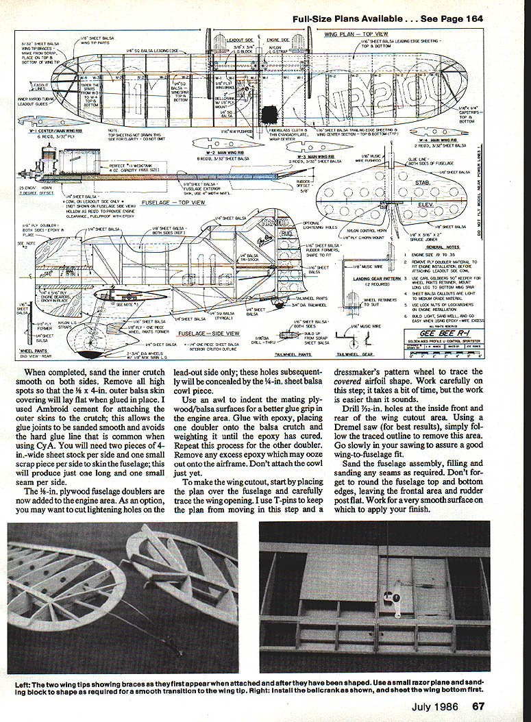
- Cut major components (except cap strips) before assembly. Block‑sand ribs in stacks for uniformity. Drill lead‑out holes in ribs per plan and apply thin CyA around hole perimeters for strengthening.
- Cover the plan with wax paper and pin it to a flat building board. Assemble the left panel (lead‑out side) first: pin and glue bottom trailing edge (TE) and ribs W‑1 through W‑3 to the plan, glue the 1/4‑in. sq. balsa leading edge (LE) to ribs, add top spar and top TE (leave between W‑3 and W‑4 unglued), then glue the bottom spar on the reverse side.
- Position W‑4 without gluing initially (its spar notches are undersized to allow later tapering). Glue the tip pieces together, fit, and glue to LE, W‑3, and W‑4 using thick CyA. Glue the TE between W‑3 and W‑4 to the tip.
- Taper top and bottom spars between W‑3 and W‑4 flush with W‑4 edge. Add 3/32 sheet balsa wing tip braces, 1/8‑in. plywood wing braces, and landing gear block.
- On the lead‑out side only: add bellcrank mounting parts, bellcrank, music‑wire pushrod, and Nyrod tubing lead‑out guides.
- Build the right wing panel similarly. Join panels with epoxy and clamp until cured. Sand and prepare for sheeting.
- Add bottom center‑section sheeting, top center sheeting (making pushrod cutouts), bottom LE and top LE sheeting, then cap strips to top and bottom of ribs. Consider wrapping the two‑piece wing center with fiberglass cloth and thin CyA for strength.
- Sand smooth. Attach the wing to the fuselage when ready using a strong joint (epoxy or thick CyA), and align squarely per the plan.
Wheel Pants
- Wheel pants comprise three pieces: an internal plywood former and two balsa outer skins (upper and lower).
- Cut the 1/8‑in. plywood former to full outline. Glue the 1/16‑in. upper skin to the plywood former, and glue the 1/4‑in. teardrop‑shaped lower balsa piece to the former. Allow to dry.
- Final‑sand and round all edges except the top, which should match wing contour. Sand intersections and fill as required for a smooth transition.
- Construct the other wheel pant as a mirror image (left and right).
- Form landing gear struts per plan. When installing wheel pants, secure them to the struts without the wheels for easier alignment.
- Pre‑locate landing gear clips to wheel pants and start screws into the plywood. Run screws through clips and wheel pants, filing or trimming any protruding screw length.
- Place the model upside down in a cradle for support. Secure upper clip first, rotate pant as needed, then attach the lower clip. When nearly tightened, orient the pant parallel to the fuselage and finish tightening.
- Position and screw the Goldberg 90° keeper per plan (long leg to wing spar, short leg to plywood side of pant) to help prevent rotation. After finishing, place a drop of thick CyA on each wheel pant screw before final installation.
Tail Wheel Enclosure
- Shape the inner former section as shown on the plan and cut out the wheel area carefully to avoid breaking balsa.
- Sand the assembly to profile, following plan contours and preserving side thickness while shaping front and rear.
- Drill the 1/16‑in. hole for the tail wheel gear and check fit. The author used a Perfect #61 3/16‑in. balloon wheel.
Finish
- Finish choice is up to the builder. The author used white Super MonoKote and red Solarfilm, with the cockpit area in chrome MonoKote and black MonoKote trim lines.
- To duplicate scales, numerals, and accents, place the plan over covering material and cut them out with a sharp #11 blade and metal straightedge, working over scrap plywood for support. Add panel lines, flying wires, or other details as desired.
Flying
- Before flying, check everything is secure: engine, tank, wheel pants, etc. Verify lead‑out lines and pushrod function with no binding.
- Balance the model slightly nose‑down with no fuel in the tank. Ensure the model tracks straight for clean takeoffs.
- For initial flights, take it easy for the first laps; the model is responsive. It performs well in wingovers and shows off in the air.
I hope you enjoy constructing and flying your Gee Bee R‑1 profile model as much as I did. Fly safely and share the hobby with someone new.
Bill of Materials
- Five 1/4 x 3/4 x 36 in balsa sticks (fuselage crutch, wing)
- Two 1/4 x 3/4 x ? in plywood (engine bearers)
- Three 1/8 x 3 x 36 in balsa sticks (cap strips)
- One 1/4 x 1/2 x 36 in spruce joiner (elevator)
- Two 1/8 x 1/4 x 36 in (landing gear block w/ 1/8‑in. groove)
- Three 1/8 x 3 x 36 in balsa sheet (rudder, wing sheeting)
- One 1/4 x 3 x 36 in balsa sheet (fuselage exterior)
- Two 1/8 x 4 x 36 in balsa sheet (fuselage crutch, sheeting)
- One 1/4 x 3/4 x 12 in plywood sheet (cowl)
- One 1/8 x 12 x 12 in plywood sheet (cowling dowel)
(Note: follow the plan for any additional small parts, hardware, blind nuts, hinges, bellcrank, pushrod, Nyrod, wheel, and covering materials.)
Transcribed from original scans by AI. Minor OCR errors may remain.

