
PROFILE JU-635
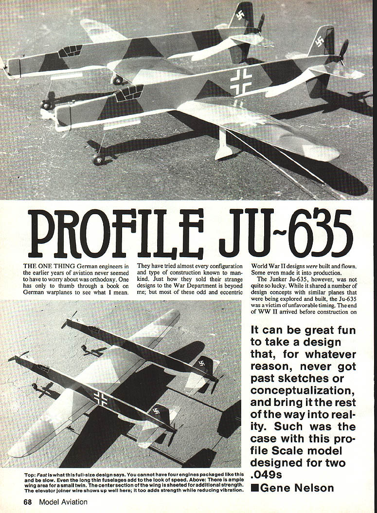
Profile scale model designed for two .049s — Gene Nelson
Background
The one thing German engineers in the earlier years of aviation never seemed to worry about was orthodoxy. Thumb through a book on German warplanes and you'll see what I mean — they tried almost every configuration and type of construction known to aviation. Many odd and eccentric World War II designs were built and flown; some even reached production. The Junkers Ju-635, however, was a victim of unfavorable timing: the end of WWII arrived before construction on a prototype could begin, and the design never got past sketches and conceptualization.
It can be great fun to take a design that never left the drawing board and bring it the rest of the way into reality. Such was the case with this profile model of the Ju-635.
Zwilling (twin) configuration
Prominent among the design concepts the Ju-635 shared with other warplanes of the period was the zwilling (twin) configuration — taking two aircraft and joining them with a common center wing. Examples:
- Heinkel He 111Z: two He 111 bombers joined by a new center wing and fitted with a fifth engine to tow large gliders.
- Messerschmitt Bf 109Z: two Bf 109s joined; it was completed very late and destroyed before flying.
- North American F-82: often thought to be two P-51 Mustangs joined together, but actually a new airframe designed to use the benefits of the zwilling layout.
The Ju-635 made authentic use of the zwilling concept, but with notable originality.
Ju-635 and the Dornier Do 335
The Ju-635 concept mated two Dornier Do 335 airframes. The Dornier Do 335 was radical for its day — the largest fighter of its era and the only operational inline push-pull twin-engined fighter built. It featured unusual items such as ejector seats, tricycle landing gear, and heavy armament.
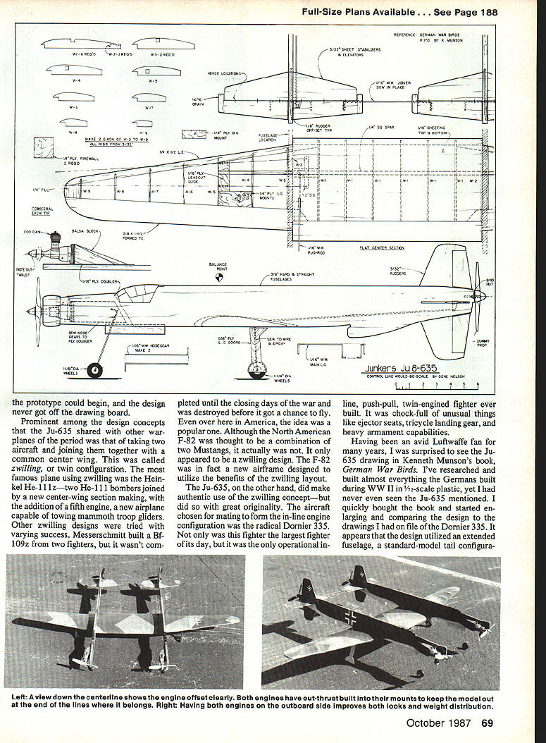
Research into Kenneth Munson's German Warbirds revealed a Ju-635 drawing. Comparing that drawing with Dornier Do 335 plans suggested the Ju-635 used an extended fuselage, a standard-model tail configuration, and Do 335 wings. The center-section chord is significantly wider than the standard wing root. Piecing together side views produced a model believed to be largely accurate given the limited source material.
As a modeler, the goal was to capture the essence: long narrow fuselages, four-legged gear, and a distinctive silhouette. Powering both props with shaft extensions was considered but would have made the project overwhelming, so the choice was made to use freewheeling rear props.
Model construction
Construction is straightforward but requires attention to alignment because of long nose and tail moment arms. The two fuselages must be parallel in both side and plan views. The model is designed to key together: slots are built into the center wing to fit the fuselages. Pin the wing to a large, flat surface during final assembly and set the fuselages into their slots, aligning carefully before gluing.
Materials and preparation
- Build two of nearly every part: fuselages, rudders, stabilizers, elevators, etc.
- Use straight, firm sheets of 3 x 3/8 in. balsa for fuselages.
- Prepare plywood firewalls, plywood nose doublers, and engine mount blocks.
- Use 1/16 in. music wire for the elevator joiner and landing gear wires.
- Cyanoacrylate (CYA) recommended for rapid bonding where noted.
Control surfaces and tail
- Cut out four rudders, two elevators, and two stabilizers.
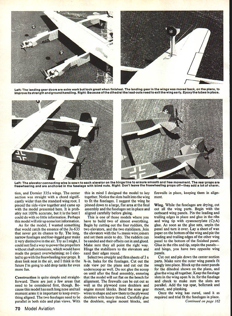
- Join the elevators with the 1/16 in. music wire joiner; tack with CYA and sew to the elevators as shown on the plans. Bend and finish the joiner, then finish-glue it in place.
- Sand and cut rudder offsets, glue in place, and confirm correct orientation.
- Hinge stabilizers to elevators and round all leading/trailing edges.
Fuselages
- Cut the side view of each fuselage from the balsa sheets and cut out the underscoop. Do not glue the scoop cap until after final assembly so the model can sit flat on the bench for alignment.
- Cut and fit firewalls, plywood nose doublers, and engine mount blocks.
- Bend nose gear wires to shape and sew them to the plywood doublers using heavy thread.
- Carefully glue doublers, engine mount blocks, and firewalls in place, keeping everything aligned.
Wings
- Cut out all wing parts, beginning with the outboard wing panels.
- Pin leading and trailing edges and glue ribs and wing tip with CYA. As soon as glue sets, unpin the panel and turn it over.
- Lay wax paper under the finished panel, pin the leading and trailing edges of the opposite panel to the bottom of the finished panel, glue in ribs and tip, unpin — you now have two opposite wing panels.
- Cut out and pin the center section parts. Ensure outer wing panels fit snugly into place.
- Block up the outer panels for the dihedral shown on the plans and glue the whole wing together. Keep the fuselage slots properly positioned and parallel.
- Add the top spar, bellcrank and mount, and planking.
- Once the wing cures, sand as required and trail-fit the fuselages into the slots.
Landing gear and final fuselage items
- Cut plywood landing gear doors and seal with several coats of dope.
- Bend main landing gear wires to shape and sew the gear doors to the wires as shown.
- Add lower scoops, nose gear doors, main landing gears, and lower rudders to the fuselages.
- Install engines, wheels, and rear props. Add a drop of CYA to rear prop screws to keep them from coming off in flight.
- Balance the model and add weight if required.
Finishing
- Paint in a common Luftwaffe splinter pattern: light blue undersides and dark green/black-green upper surfaces.
- Paint canopies black and outline with white pin-striping tape for highlights.
- Cut crosses from black and white MonoKote trim sheets and stick in place.
- Consider adding drop tanks for appearance and flight endurance.
Flying tips
- Test-run engines on the bench before flying. They should start and run well individually and together.
- Try tuning engines to the same pitch and timing their runs. The longer-running engine should be in the inboard fuselage.
- Use about 30-ft steel control lines for flight (this model was designed for control-line operation).
- Warm up engines, set needle valves in harmony, shut down, refuel, and hook up the lines.
- The Ju-635 rolls out rather awkwardly on four wheels but accelerates quickly and will lift off with a touch of elevator.
- In the air it is stable and maneuverable. On one engine it will settle to a slow, steady flight but remains responsive.
Twins are a lot of fun to fly, but field adjustments can be fiddly. Proper preflight checks and engine tuning will make flying this unusual, never-realized design a rewarding experience. Have fun reliving a past that never got to happen.
Transcribed from original scans by AI. Minor OCR errors may remain.

