
Profile Stearman PT-17
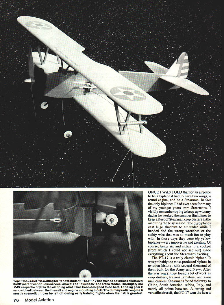
Once I was told that for an airplane to be a biplane it had to have two wings, a round engine, and be a Stearman. In fact the only biplanes I had ever seen for many of my younger years were Stearmans. I vividly remember trying to keep up with my dad as he worked the summer flight lines to keep a fleet of Stearman crop dusters in the air during the busy season. The big biplanes cast huge shadows to sit under while I handed dad the wrong wrenches or the safety wire that was so much fun to play with. In those days they were big yellow biplanes—very impressive and exciting. Of course, being six and sitting in a cockpit (from which I could not see out) made everything about the Stearmans exciting.
The PT-17 is a truly classic biplane. It was probably the most-produced biplane in aviation history, with several thousand of them built for the Army and Navy. After the war years, they found a lot of work as crop dusters, trainers, stunt planes, and even mail carriers. Stearmans found their way to China, South America, Africa, Italy, and nearly all points between. A strong and versatile aircraft, the PT-17 won the hearts of millions of pilots. Today it is one of the most popular and recognized biplanes still flying.
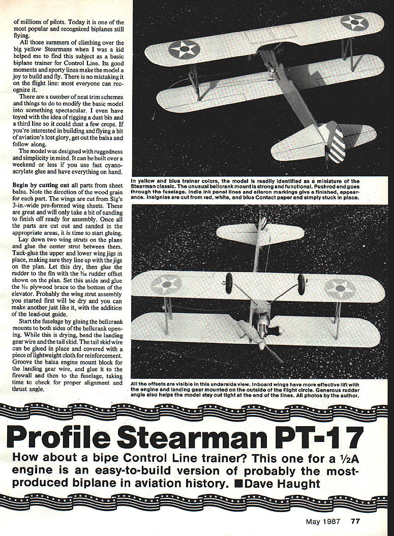
All those summers of climbing over the big yellow Stearmans when I was a kid helped me to find this subject as a basic biplane trainer for Control Line. Its good moments and sporty lines make the model a joy to build and fly. There is no mistaking it on the flight line: most everyone can recognize it.
There are a number of neat trim schemes and things to do to modify the basic model into something spectacular. I even have toyed with the idea of rigging a dust bin and a third line so it could dust a few crops. If you're interested in building and flying a bit of aviation's lost glory, get out the balsa and follow along.
Model overview
The model was designed with ruggedness and simplicity in mind. It can be built over a weekend or less if you use fast cyanoacrylate glue and have everything on hand.
Materials and preparation
- Sheet balsa parts (note wood grain direction for each part)
- Sig 3-in. pre-formed wing sheets (for wings)
- 1/16" rudder offset, 1/32" plywood brace
- Landing gear wire, tail skid wire
- Bellcrank hardware, aluminum tube spacers, spade bolts
- RC nylon hinges, control horns, clevis rods, soft copper wire
- Slow-set epoxy, CA (cyanoacrylate), Loc-Tite
- 1/2-in. hardwood dowels for cabane struts
- Thinned dope, paint, finish materials
- Optional: dummy engine materials (1/2-in. dowels, heavy thread, pine crankcase block), wheels (e.g., Williams Brothers)
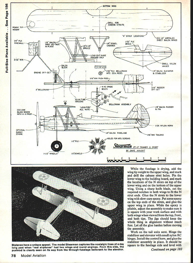
Begin by cutting out all parts from sheet balsa. Note the direction of the wood grain for each part. The wings are cut from Sig's 3-in.-wide pre-formed wing sheets. These are great and will only take a bit of sanding to finish off ready for assembly. Once all the parts are cut out and sanded in the appropriate areas, it is time to start gluing.
Wing assembly
- Lay down two wing struts on the plans and glue the center strut between them.
- Tack-glue the upper and lower wing jigs in place, making sure they line up with the jigs on the plan. Let this dry.
- Glue the rudder to the fin with the 1/16" rudder offset shown on the plan. Set this aside.
- Glue the 1/32" plywood brace to the bottom of the elevator.
- The first wing strut assembly you started will probably be dry; make another just like it, adding the lead-out guide to the second assembly.
Fuselage and landing gear
- Start the fuselage by gluing the bellcrank mounts to both sides of the bellcrank opening.
- While this is drying, bend the landing gear wire and the tail skid.
- Glue the tail skid wire in place and cover with a piece of lightweight cloth for reinforcement.
- Groove the balsa engine mount block for the landing gear wire, and glue it to the firewall and then to the fuselage, taking time to check for proper alignment and thrust angle.
Installing wings and N-struts
- While the fuselage is drying, add the wing tip weight to the upper wing, and mark and drill the cabane strut holes.
- Pin the lower wing to the building board, and mark the locations of the N-struts on top of the lower wing and on the bottom of the upper wing.
- Using a sharp knife blade, cut the required notches in both wings to fit the N-strut ends.
- Glue the N-struts to the lower wing with slow-cure epoxy.
- Put some epoxy on the top ends of the struts, and glue the upper wing in place.
- While the epoxy is pliable, adjust the assembly to make sure it is square with your work surface and with both wings when viewed from the top, front, and both tips. The jigs should keep the whole thing in alignment without much fuss.
- Let all the glue harden before moving the assembly.
Tail units and bellcrank
- Hinge the stabilizer and elevator with small nylon RC hinges.
- Install the control horn, and glue the stabilizer assembly in place. It should be square to the fuselage side and level with the wings.
- Add the rudder and vertical fin assembly, also making sure it is true.
- While the glue is drying, begin the bellcrank assembly.
- Cut two small aluminum tube spacers, and assemble the bellcrank unit as shown in the exploded view on the plans.
- Drill the two holes in the plywood mounts to fit the spade bolts, and slide the unit into place.
- Trim the fuselage slot to clear the bellcrank as it swings its full arc.
Slide out the bellcrank unit, and make up the lead-outs. Attach them only to the bellcrank at this time; the line ends can be formed after final assembly of the wings to the fuselage. Install the bellcrank permanently, adding Loc-Tite or a drop of CA to each nut to keep it from loosening.
Pushrod and control linkage
The pushrod can now be bent to fit. I use two RC clevis rods, attaching one to the bellcrank and the other to the elevator horn. By cutting off each of them so they overlap one another by 3/16 in., they can be wrapped with soft copper wire, adjusted to the proper length, and then soldered in place. This eliminates all the "fun" of trying to bend a wire to exact length.
Final assembly
At this point the model consists of two completed subassemblies: wings and fuselage. Fit the lower wing to the fuselage, trimming the engine mount block to fit the wing leading edge. When satisfied with the fit, add the slow-set epoxy to glue the wing/fuselage assemblies together. Check the wing alignment and incidence one last time, then set it aside for the epoxy to cure.
While the model rests, plan out the color scheme and cut four 1/2-in. hardwood dowels 2 in. long for the cabane struts. When the epoxy on the wing joint has cured, carefully pre-drill the holes in the top wing at the angle required for the cabane struts. Trim the dowel ends to the appropriate angle to fit the fuselage, and glue the struts in place with epoxy. Once the epoxy is dry, sand the entire model and apply two to three coats of thinned dope. Finish-sand the wood, and apply your colors.
Dummy engine, wheels, and balance
Two of the three "requirements" for a biplane are now evident: it's a Stearman, and it has two wings. Are you going all the way and also giving it a round engine? The dummy engine adds a lot to the appearance of the finished model, but it takes a bit of extra time.
- I cut seven lengths of 1/2-in. dowel for the cylinders, wrapped them with heavy thread, and secured them to a pine crankcase block that was drilled out to fit over the Cox .049 crankcase.
- This was then painted black and screwed to the nose of the model with long wood screws. With this mounting it is easy to remove the dummy engine for grass-field flying and engine maintenance.
- A nice set of smooth-contour 1-1/2-in. wheels that look right at home on the Stearmans are made by Williams Brothers.
Add your wheels, engine, and propeller, and check whether your Stearman balances as shown on the plan. If it needs nose weight to achieve the proper balance, add it; if it is a bit nose-heavy, don't worry at this point. Finish off the lead-outs; thread them through the holes in the N-strut guide, and form the eyelet ends per drawings in the AMA rule book.
Flying tips
It's time to find a field to dust. I always fly 1/4A models on steel lines; they fly so much better and are safer. Hook up a set of 30-ft. lines, fuel the tank, and start the engine. The Stearman is a spunky flier and a lot of fun.
If you haven't treated yourself to a Control Line biplane before, this one is sure to please. To tone it down a bit for training flights, try putting the prop on backwards and use 35-ft. lines. This will help slow it down without cutting the flight performance very much.
Just think how the guys at the club will react when you tell them you've just soloed your Stearman and are thinking about taking up aerobatics or crop dusting with it. Have fun, and keep 'em flying!
Transcribed from original scans by AI. Minor OCR errors may remain.

