
Project 1991
By Richard Slate
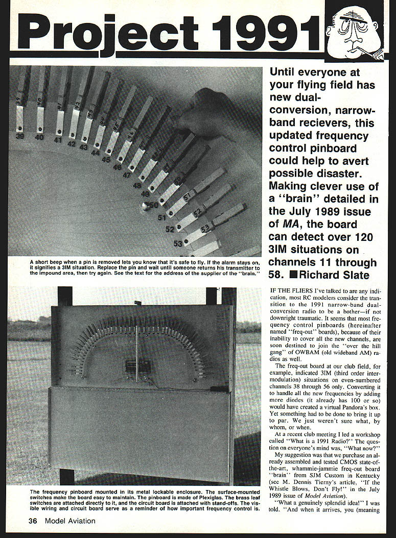
Until everyone at your flying field has new dual-conversion, narrow-band receivers, this updated frequency-control pinboard could help avert possible disaster. Making clever use of a "brain" detailed in the July 1989 issue of Model Aviation, the board can detect over 120 3IM (third-order intermodulation) situations on channels 11 through 58.
IF THE FLIERS I've talked to are any indication, most RC modelers considered the transition to the 1991 narrow-band dual-conversion radios to be a bother—if not downright traumatic. It seemed that most frequency-control pinboards ("freq-out" boards) were soon destined to join the "over the hill gang" of OWBAM (old wideband AM) radios because of their inability to cover the new channels.
The freq-out board at our club field, for example, indicated 3IM situations on even-numbered channels 38 through 56 only. Converting it to handle all the new frequencies by adding more diodes (it already had 100 or so) would have created a virtual Pandora's box. Yet something had to be done to bring it up to par.
At a recent club meeting I led a workshop called "What is a 1991 Radio?" The question on everyone's mind was, "What now?" My suggestion was that we purchase an already assembled and tested CMOS state-of-the-art freq-out board "brain" from SJM Custom in Kentucky (see M. Dennis Tierney's article "Whistle Blows, Don't Fly" in the July 1989 issue of Model Aviation).
The ordered board arrived in due course, almost ready to install — a marvel of technology capable of sorting out over 120 3IM situations on channels 11 through 58. After looking it over I could plainly see the design criteria: top quality, simplicity, and low cost.
Plan and first subprojects
Our plan was to wipe out the easy subprojects first.
- Install an alarm system (the "brain" included a neat little wiring diagram showing how to make a buzzer buzz).
- Design and build the new pinboard on Plexiglas.
- Build corrosion-resistant leaf switches and wire each channel to the board.
- Enclose the assembly in a lockable cabinet and provide reliable power and charging.
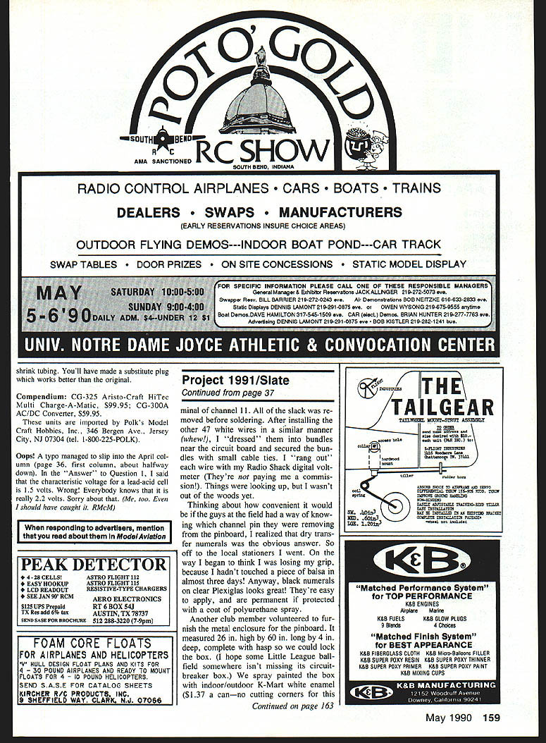
Installing the alarm was a piece of cake. Fifteen minutes later and a few dollars poorer, I had the parts I needed: a Radio Shack NPN transistor, type 2N2222 (easily soldered in place after drilling three holes in the left side of the board per the instructions), and the alarm buzzer itself.
Hookup is basic: solder long red to long red and long black to long black for the board locations and the 4.8-volt battery-box connections.
Pinboard construction
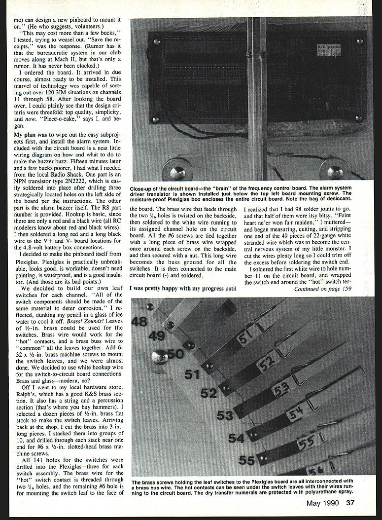
I decided to make the pinboard itself from Plexiglas. Plexiglas is practically unbreakable, looks good, is workable, doesn't need painting, is waterproof, and is a good insulator.
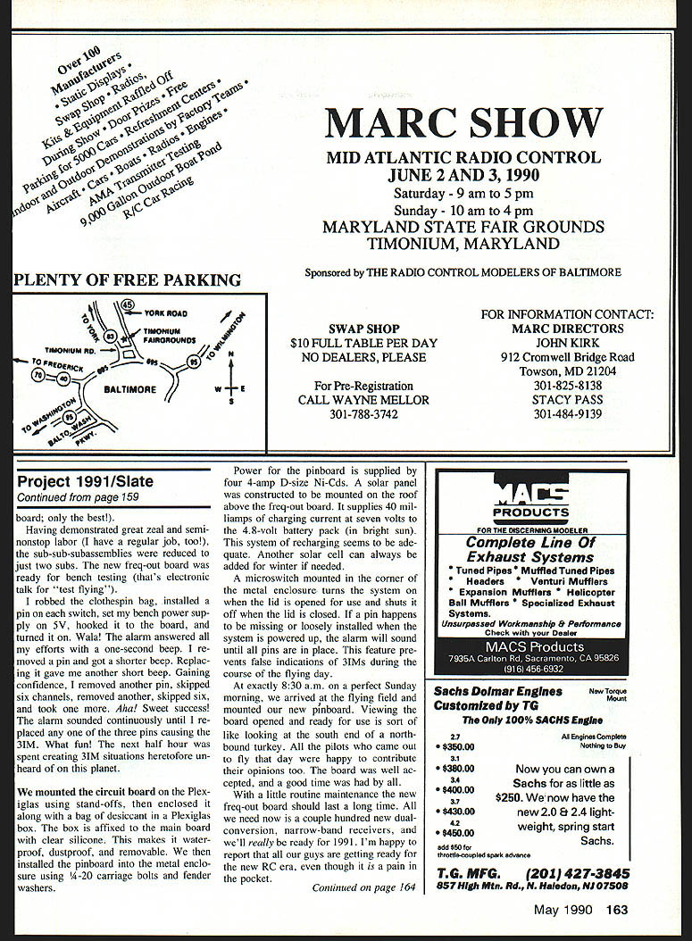
To keep corrosion problems to a minimum, I built my own leaf switches. Channel-switch components should be made from the same material to deter corrosion. Brass leaves work well; brass wire serves as the hot contacts and brass buss wire ties the common leaves together. Use #6-32 x 1/2-in. brass machine screws to mount the switch leaves. I chose white hookup wire for the switch-to-circuit-board connections.
Materials (typical):
- Brass flat stock for switch leaves
- Brass wire for hot contacts and buss
- #6-32 x 1/2-in. brass machine screws
- 22-gauge white stranded hookup wire
- Plexiglas sheet for the board
- Stand-offs for mounting the circuit board
- Small cable ties, desiccant, clear silicone
I bought brass flat stock, cut it into 3-in. pieces, stacked them in groups of ten, and drilled through the stacks near one end for the #6 slotted-head brass machine screws. Holes for the switches were drilled in the Plexiglas. For each three-switch assembly, the brass-wire hot-switch contact was threaded through two small holes; the remaining #6 hole mounted the switch leaf to the face of the board.
The brass wire feeds through two 1/16-in. holes, is twisted on the backside, and soldered to the white hookup wire running to its assigned channel hole on the circuit board. All the #6 screws are tied together with a long piece of brass wire wrapped once around each screw backside and secured with a nut. This long wire becomes the buss ground for all the switches and is connected to the main circuit board (-) and soldered.
Wiring the channels
I measured, cut, and stripped 49 pieces of 22-gauge white stranded wire to become the central nervous system of the board. I left the wires a bit long so I could trim the excess before soldering the switch end.
I soldered the first white wire to the hole numbered 11 on the circuit board and wrapped the switch end around the hot switch terminal of channel 11. All slack was removed before soldering. After installing the other 47 white wires in a similar manner, I dressed them into bundles near the circuit board and secured the bundles with small cable ties. I "rang out" each wire with my Radio Shack digital voltmeter to verify continuity.
Thinking about how convenient it would be if pilots knew which channel pin they were removing from the pinboard, I applied dry-transfer numerals to the Plexiglas. Black numerals on clear Plexiglas look great and are easy to apply; they are permanent if protected with a coat of polyurethane spray.
Enclosure and mounting
Another club member volunteered a metal enclosure for the pinboard. It measured about 26 in. high by 60 in. long by 4 in. deep and hadp so we could lock it. We spray-painted the box with indoor/outdoor white enamel.
We mounted the circuit board on the Plexiglas using stand-offs, then enclosed it along with a bag of desiccant in a Plexiglas box affixed to the main board with clear silicone. This makes the electronics waterproof, dustproof, and removable. The pinboard assembly was installed into the metal enclosure using 1/4-20 carriage bolts and fender washers.
A microswitch mounted in the corner of the metal enclosure turns the system on when the lid is opened for use and shuts it off when the lid is closed. If a pin is missing or loosely installed when the system is powered up, the alarm will sound until all pins are in place — preventing false indications of 3IMs during the flying day.
Power and charging
Power for the pinboard is supplied by four 4-amp D-size Ni-Cads (4.8V). A solar panel on the roof above the freq-out board supplies about 40 milliamps of charging current at seven volts to the battery pack in bright sun. This charging rate has proved adequate; another solar cell can be added for winter if needed.
Bench and field testing
For bench testing I installed a pin on each switch, set my bench power supply to 5V, hooked it to the board, and turned it on. Voila! The alarm answered with a one-second beep. Removing a pin gave a shorter beep; replacing it returned the short beep. I then removed pins in various combinations to create 3IM situations. The alarm sounded continuously when three pins caused a 3IM until any one of the three pins was replaced — exactly the behavior we wanted.
At 8:30 a.m. on a perfect Sunday morning we mounted the new pinboard at the flying field. The board was well accepted by the pilots, who were happy to offer opinions. A good time was had by all.
Maintenance and wrap-up
With routine maintenance the new freq-out board should last a long time. All we need now is a couple hundred new dual-conversion, narrow-band receivers, and we'll really be ready for 1991. I'm happy to report that the guys at our field are getting ready for the new RC era, even though it is a pain in the pocket.
Transcribed from original scans by AI. Minor OCR errors may remain.

