
Project Extra
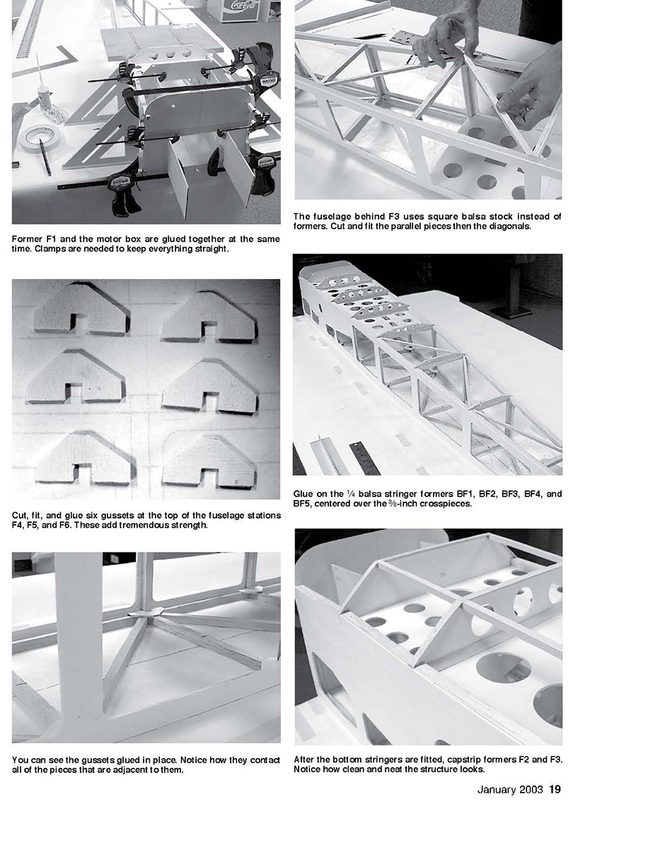
Glue on the 1/4-inch balsa stringer formers BF1, BF2, BF3, BF4, and BF5, centered over the 3/8-inch crosspieces.
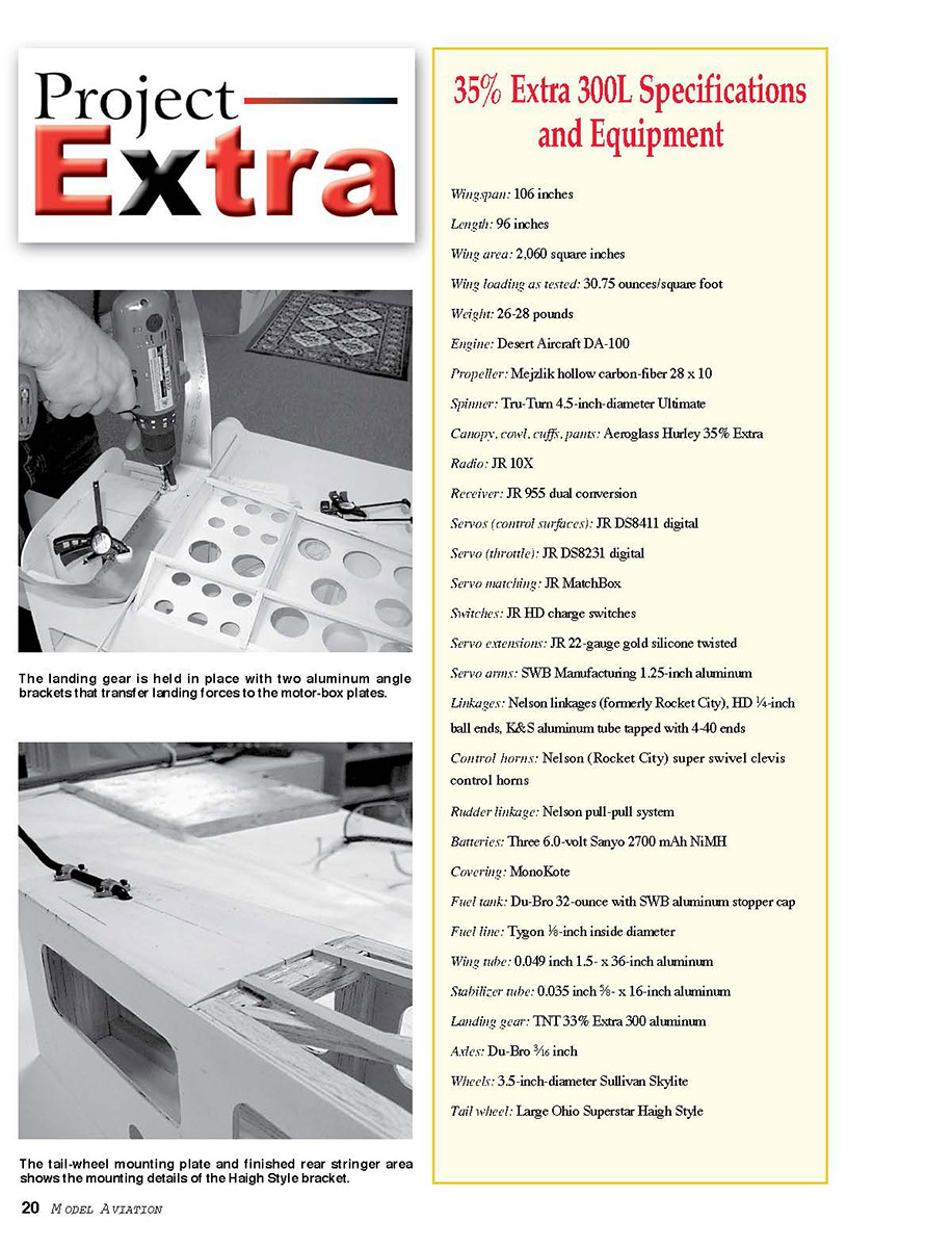
The fuselage behind F3 uses square balsa stock instead of formers. Cut and fit the parallel pieces, then the diagonals. The landing gear is held in place with two aluminum angle brackets that transfer landing forces to the motor-box plates. The tail-wheel mounting plate and finished rear stringer area illustrate the mounting details of the Haigh-style bracket.
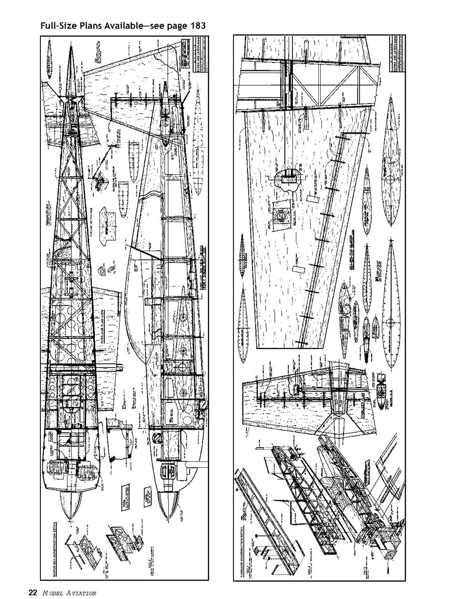
The landing gear has been angled forward to help change the twisting force from landing to a more survivable compression force, and aluminum "L" brackets transfer the load to the motor box, eliminating the need for a heavy plywood plate. The original prototype was built with a motor box that captured the wing tube. With that design, vibration from the engine was transferred more directly to the wings, wreaking havoc on ailerons, hinges, servos, and linkages. Designs that did not capture the tube seemed to be much smoother, so in the second design the motor box was stopped short of the wing tube. It worked: the wingtips and ailerons vibrate much less, and the hardware experiences less wear and tear.
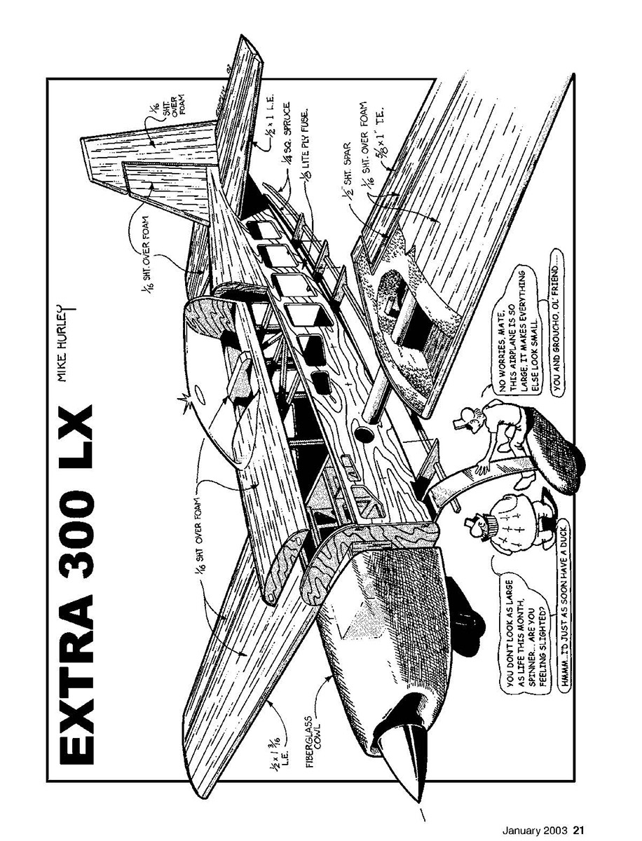
One of this design’s unique qualities is the extensive use of laminated balsa over long expanses of thin, light plywood. The process creates a strength in shear that outweighs the sum of the two materials and makes the structure light while keeping it rigid. The full-scale Extra is slightly rounded at the front, but for ease of construction an angular nose was used at the center section. The fuselage sides form a long triangle from the rear of the cowl to the tail; slight angles were added to fill out the shape and smooth the transition from the cowl to the fuselage without adding complexity or weight.
In IMAC, percentage of full scale is calculated using the wingspan. The full-scale Extra has a wingspan of 25 feet, 3 inches, giving a 35% span of 106 inches for this model. The wing planform, root and tip chords, and overall length are kept at 35% scale, while the fuselage width was reduced slightly to about 33% for a sleeker look, lower weight, increased rigidity, and slightly reduced drag.
The number-two prototype (the finished one shown in the article) weighed 27.5 pounds ready to fly. A large wing area of 2,060 square inches gives a light loading of 30.75 ounces per square foot. Even at mile-high altitude in Colorado, the Desert Aircraft DA-100 engine pulls the airplane aggressively; at sea level the combo would be very powerful. In normal flight the airplane floats like a glider, and for 3-D it's slow and agile.
A third rendition aims for even lighter weight by opening up the fuselage sides, eliminating rear formers, and using more selective wood, including contest-grade balsa sheeting except for the main wings. The goal is to reduce weight to about 26.5 pounds, bringing wing loading into the low 20s.
35% Extra 300L Specifications and Equipment
- Wingspan: 106 inches
- Length: 96 inches
- Wing area: 2,060 square inches
- Wing loading as tested: 30.75 ounces/square foot
- Weight: 26–28 pounds (prototype 27.5 lb; target ~26.5 lb)
- Engine: Desert Aircraft DA-100
- Propeller: Mejzlik hollow carbon-fiber 28 x 10
- Spinner: Tru-Turn 4.5-inch diameter
- Canopy, cowl, cuffs, pants: Aeroglass Hurley 35% Extra
- Radio: JR 10X
- Receiver: JR 955 dual conversion
- Servos (control surfaces): JR DS8411 digital
- Servo (throttle): JR DS8231 digital
- Servo matching: JR MatchBox
- Switches: JR HD charge switches
- Servo extensions: JR 22-gauge gold silicone twisted
- Servo arms: SWB Manufacturing 1.25-inch aluminum
- Linkages: Nelson linkages (formerly Rocket City), HD 1/4-inch ball ends, K&S aluminum tube tapped with 4-40 ends
- Control horns: Nelson (Rocket City) super swivel clevis control horns
- Rudder linkage: Nelson pull-pull system
- Batteries: Three 6.0-volt Sanyo 2700 mAh NiMH
- Covering: MonoKote
- Fuel tank: Du-Bro 32-ounce with SWB aluminum stopper cap
- Fuel line: Tygon 1/8-inch ID
- Wing tube: 0.049-inch, 1.5 x 36-inch aluminum
- Stabilizer tube: 0.035-inch, 5/8 x 16-inch aluminum
- Landing gear: TNT 33% Extra 300 aluminum
- Axles: Du-Bro 3/16 inch
- Wheels: 3.5-inch-diameter Sullivan Skylite
- Tail wheel: Large Ohio Superstar Haigh style
The Design
This airplane's design is conventional and comparable to other SA aircraft. It was specifically designed around Desert Aircraft's twin-cylinder 100cc gas engine—light, powerful, reliable, with excellent customer service.
Wings and stabilizers are each two-piece and removable for transport and storage; they slide onto the 0.049-inch, 1.5 x 36-inch aluminum wing tube that is bonded into the wing. The stabilizer uses the 0.035-inch, 5/8 x 16-inch aluminum tube. The fuselage sides are 1/8-inch light plywood almost 70 inches long—source locally or from specialty plywood distributors.
The cowl, wheel pants, canopy, and landing-gear cuffs are from Aeroglass. FlyingFoam.com offers high-quality CNC-cut foam parts (foam wings, stabilizers, hatch, turtledeck), though templates are on the plans if you prefer to cut your own foam. The 1.5-inch x 36-inch .049 wing tube, 5/8-inch x 16-inch .035 stabilizer tube, and landing gear are from TNT Landing Gear Products; they supply phenolic sockets for construction.
The airframe is primarily balsa and light plywood with only three aircraft-plywood pieces: the motor-box sides and the landing-gear plate.
Erik Richard will be constructing this airplane for demonstration purposes. Erik has lifelong experience building and designing model aircraft; his father was an aeronautical engineer and avid model builder. This design has evolved through testing; many good changes come from those results.
In a model of this size and power, equipment and hardware must be robust. Pay attention to linkages and fasteners, and don’t skimp on quality servos or electronics.
CONSTRUCTION
A few notes about the plans before you begin:
- Sheet three shows two different hole sizes for the wing-tube socket on the fuselage side because two different sockets are used. Measure your socket with a caliper and cut the hole slightly undersized; sand to a snug fit. Do this with both fuselage sides taped together to ensure exact alignment.
- The plans show the alignment dowel at 90° to the wing root. That’s fine for the wing hold-down bolt, but orient the dowel parallel to the wing so it can slide into place without binding when installing the wing.
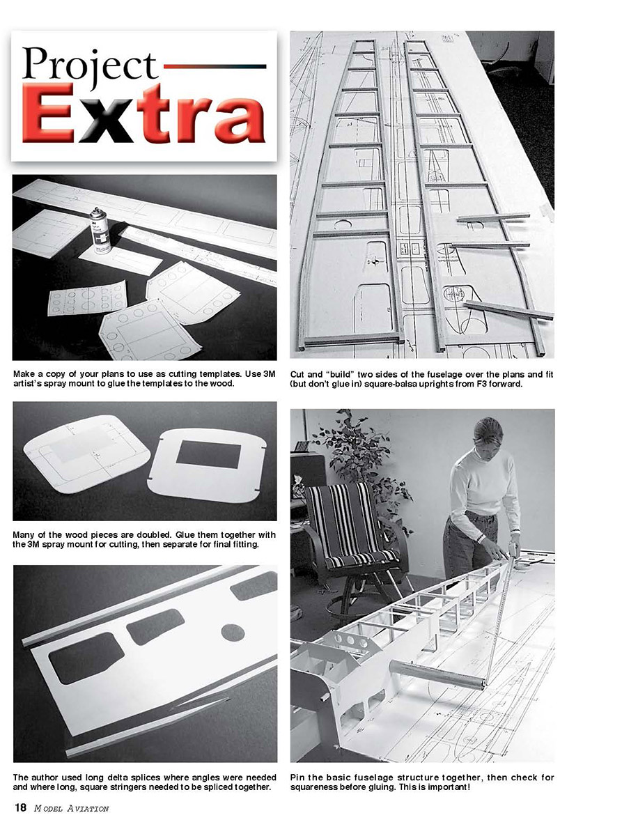
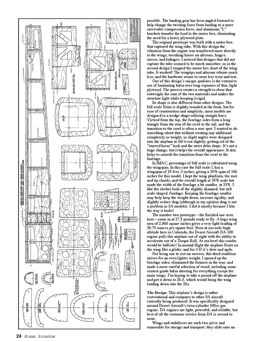
- Make a copy of your plans to use as cutting templates. Cut from the plans the formers, fuselage sides, fuselage floors, motor box, landing-gear plate, tail-wheel plate, cowl former, and stringer stock.
- Tape two pieces of 1/8 x 7/8-inch light plywood together for the fuselage sides and two pieces of 12 x 12-inch for the cowl former and F1. Tape approximately 20 x 9-inch aircraft plywood together for the motor-box sides. Temporary spray glue helps keep parts aligned while cutting.
Parts that need to be cut out:
- 1/8-inch light plywood: formers F2, F3; fuselage sides; fuselage floors (FLO, F1L, F2L, F3L); cowl former and F1; tail-wheel plate
- 1/8-inch balsa: BF1, BF2, BF3, BF4, BF5, stringers and caps
- 1/4-inch aircraft plywood: landing-gear plate, motor-box sides, firewall
Use 3M artist’s spray mount 6065 to glue the cut plans to your wood. On the fuselage sides, cut to the outside edges (the landing-gear plate glues between the motor-box sides). Radiused the lightening-hole corners to 3/16-inch and use an adjustable hole saw for the wing tube & socket diameter; cut and sand both pieces while glued together so they match.
After cutting and before removing the paper template, mark centers on the part edges. After removing the paper, sand the part lightly to remove glue residue, label the part, and mark the centerline.
The cowl former and F1 can be cut and sanded together to the outside line. Scribe an alignment line at the top and bottom, separate the parts, glue the second template to the part, and cut the inside lines on both parts. The cowl former will be split later.
Finishing (fuselage interior and longerons):
- Splice together four pairs of 3/8 x 3/8-inch square balsa to form the longerons laminated to the inside of each fuselage side. Use a long delta splice for the bottom front longeron that angles up.
- Glue on the longerons, and cut and glue the 3/8-square upright fuselage structure from F3 rearward (forward pieces glued later).
- Cut and fit the forward 3/8-square upright fuselage structure to be used as former gussets—ensure they contact all adjacent pieces.
- Cut, fit, and glue six gussets at the top of fuselage stations F4, F5, and F6—these add tremendous strength.
- After the bottom stringers are fitted, cap-strip formers F2 and F3 to provide a neat surface for covering.
- Former F1 and the motor box are glued together at the same time; clamps are needed to keep everything straight.
- Glue the 1/4-inch balsa stringer formers BF1–BF5 centered over the 3/8-inch cross stringers.
Lay the plan on a flat surface and fold the front over the end of the table at F1. Trial-fit motor-box sides, F1, F2, F3, and fuselage sides over the plan and make final adjustments so the parts fit. Cut the fuselage floors (FLO, F1L, F2L, F3L) and fit them. Cut and fit the aft-most former and tail basket.
Cut two lengths of 3/8-square balsa to fit each former station. Mark a centerline on one piece from each station. Trial-fit and glue the whole assembly together including the forward and aft floor FLO, ensuring the fuselage is straight along the centerline. Use the wing tube & socket center hole and tube to check for square. Do not glue the phenolic wing-tube socket into the fuselage at this time.
Note: Former F1 is wider at the top than at the bottom to fit the cowl shape. The fuselage has a slight built-in twist to allow F1/cowl fit; F3 is the 90° reference for building the rear. Use weight to hold the fuselage flat on the building board.
After the fuselage alignment is correct, glue the structure together. Fit the pre-cut 3/16-inch upright former gussets next to their corresponding formers, but only glue them after the rest of the structure is aligned and glued.
After the main fuselage is glued, pin it to the table and flip it to finish fitting and gluing the remaining 3/16-inch stock structure and upright gussets at F1, F3, and along the rear of the motor box. Laminate some 1/4-square to the top inside surface of the motor-box sides as a stiffener after the firewall is installed. Finish gluing the floor (F1L) to the motor-box sides.
Do not glue the brace over F11 until after the wing-tube socket is installed.
Bottom Stringers
- Delta splice a 12-inch section onto a 48-inch length of 1/4-inch-square spruce for each 60-inch bottom stringer.
- Fit the stringers to create a flat bottom, adjusting notches as necessary to keep them straight. The stringers should follow the plan and bend at BF3. The stringers run from F2 rearward to the tail-wheel plate; sand them to fit flush at the rear.
- Add 1/16 x 1/4-inch capstrips to F2 and F3 to provide a good surface for the covering. Center the capstrip on F3; fit F2's capstrip to the rear of the former.
Landing-Gear Plate
- Cut the landing-gear plate from 1/8-inch aircraft plywood and the doublers from 1/8-inch light plywood per the plan.
- Scribe a 1/8-inch-deep line on the inside of the motor-box sides and glue the doublers to the inside of the motor-box sides, aligning them.
- Mark two points for drilling bolt holes that will attach the landing-gear "L" brackets. Cut two 4-1/2-inch lengths from one-inch, 0.050-inch-thick extruded angled "L" aluminum (available at hardware stores).
- Line up the brackets to match the top of the doubler just shy of F2. Use scrap blocks and clamps to hold and drill bolt holes while clamped. Use 6-32 cap screws with blind nuts on the outside and Loctite the assembly. Glue the landing-gear plate flush inside the motor-box sides. (Erik used lock nuts on the bracket bolts for added security.)
- With a compass, mark a line 3/4 inch inside each side of the motor box and mark the center of the landing-gear plate. Line up the landing gear and mark according to these lines. Drill four holes for 8-32 bolts. Line up the gear on the centerline of the LG plate, leaving a 3/32-inch gap between the gear and F2 (a 3/32 capstrip was used as a spacer in the prototype), and drill through the LG plate and the "L" brackets.
- Using 8-32 cap screws and lock nuts, bolt the landing gear to the fuselage. Leave the 3/32-inch gap and glue on LG1 (1/4-inch balsa former).
Tail-Wheel Plate
- Contour the tail-wheel plate edges and lighten the area as needed. The prototype removed additional wood under the stabilizer because rudder servos were mounted in the hatch compartment; this also aids maintenance and assembly. If using a heavier engine, consider mounting rudder servos in the fuselage sides under the stabilizer.
- The Ohio Superstar Haigh-type tail wheel requires an antirotation block inside the fuselage. Make the block from laminated 1/8-inch light plywood scraps—light and strong compared to hardwood.
- Mount the tail-wheel assembly with 2-56 cap screws and blind nuts set into doublers inside the tail-wheel plate. Do not use wood screws for tail-wheel brackets.
Fitting the Cowl
- Face the cowl edges with a sanding block for a good fit. Aeroglass cowls usually need only light sanding to become square. Tape the halves together.
- With a compass, mark a line on the cowl former approximately 1/32 inch (0.030 inch) from the outside and sand a little at a time, checking fit frequently until the cowl fits flush with the fuselage sides and F1.
- Mark the former to cut at the cowl seam—place marks about 1 inch apart centered on the 1/4-inch overlapping seam. Drill two 1/16-inch holes through the cowl former in place for 4-40 screws and blind nuts. Use four holes in the bottom half (spaced from inside the cowl) and three in the top half (recessed from inside the hatch). Make small doublers from 1/8-inch light plywood for the blind nuts. Do a final fit check and correct imperfections with a fillet.
- To avoid getting glue on F1, separate the cowl former from F1 with waxed paper and bolt the cowl former back onto F1. Tape the cowl in place and glue the former to the cowl with medium ZAP—be careful not to get glue between your cut marks. After the cowl is secure, remove it and add a fine fillet of Plexus Methacrylate (or similar) over the ZAP.
- With the cowl halves together, mark and drill three holes on each side for 4-40 x 1/2-inch button-head screws. Back the holes with small pieces of 1/8-inch plywood and install small 4-40 blind nuts. Nylon washers on the outside help protect paint.
- Cut the cowl ring roughly 1/8 inch on either side of the cowl half overlap, sand a beveled edge on the ring, and add Methacrylate adhesive to any unbonded areas.
- Sheet the area between F1 and LG1 with 1/16-inch balsa. The sheeting will glue to the inside of F1 and lay over the top of LG1. Sand a bevel on LG1 to line up with F1 so the sheeting lays flat. Make a 1/8-inch-wide, 1/8-inch back lip on the inside of F1 for the sheeting to bear on. Pre-glue sheets together and do half the area at a time. Use a center stringer between LG1 and F1 as a starting point and a paper template to trim to shape. Perform this with the cowl in place for proper alignment.
Odds and Ends
- Using 1/16-inch sheeting, fill the open areas on each side of the landing-gear mount at an angle. Do not fill the gap directly in front of the gear; this allows the gear to flex without breaking the balsa.
- Trace the top half of F1 onto medium-density balsa to form a stiffener for F1. Leave about 1/16 inch protruding past the top so the hatch installation and sanding align perfectly. With a compass set at roughly 1 inch, trace the outside line to form the cowl belt. Drill three relief holes for the cowl bolts using sharpened 1/16-inch-diameter copper tubing. Glue 1/8-inch aircraft-plywood washers where needed to prevent cowl bolts from pulling through the light plywood. Glue the stiffener in with the cowl completely installed to keep the former aligned.
- Glue a length of 3/8-inch square balsa into the corners of the motor box and F1 from the bottom of the motor box to the stiffener to reinforce that area.
At this point the wood portion of the fuselage for the 35% Extra 300LX is finished. The wing and stabilizer tube sockets will be aligned and glued into place after the wings and stabilizers are prepared for alignment. Subsequent steps include sheeting and trimming the foam parts.
Mike Hurley 11542 Decatur Ct. Westminster, CO 80234 mhurley@anbhi.com
Manufacturers and suppliers
- Radio equipment: JR
- JR is distributed exclusively by Horizon Hobby Inc.
- (217) 355-9511
- www.horizonhobby.com
- Engine, mufflers, propeller, wing fasteners: Desert Aircraft
- 140 S. Camino Seco, Suite 418, Tucson, AZ 85710
- (520) 722-0607
- Fax: (520) 722-5622
- www.desertaircraft.com
- Cowl, wheel pants, gear cuffs, canopy: Aeroglass
- Box 185, Langton, ON, Canada N0E 1G0
- (519) 875-1533
- Fax: (519) 875-1855
- Landing gear, wing tube, stabilizer tube: TNT Landing Gear Products, Ltd.
- 10530 Airport Hwy., Swanton, OH 43558
- (419) 868-5408
- www.tntlandinggear.com
- 4.5-inch Ultimate spinner: Tru-Turn Precision Model Products
- 100 W. 1st St., Deer Park, TX 77536
- (281) 479-9600
- Fax: (281) 479-9090
- www.tru-turn.com
- CNC cut foam parts (foam wings, stabilizers, hatch, turtledeck): FlyingFoam.com
- 1123 Doverwood St., Corona, CA 92880-1272
- (909) 371-4913
- Fax: (909) 739-0445
- www.flyingfoam.com
- Linkages, hardware: Nelson Hobby Specialties
- 2900 S.W. Cornelius Rd., Unit 762, Hillsboro, OR 97123
- (503) 259-8899
- www.nelsonhobby.com
- Plexus Methacrylate adhesive: Aerotech Models, Inc.
- 2640 Minnehaha Ave. S., Minneapolis, MN 55406
- (612) 721-1285
- www.aerotechmodels.com
Recommended similar-size Extra 300 manufacturers:
- RadioCraft Industries Inc.
- 140 S. Camino Seco, Suite 419, Tucson, AZ 85710
- (520) 886-7272
- Fax: (520) 886-4884
- www.radiocraft.com
- Aeroworks
- 401 Laredo St., Suite D, Aurora, CO 80011
- (303) 366-4205
- Fax: (303) 366-4203
- www.aero-works.net
Transcribed from original scans by AI. Minor OCR errors may remain.

