
Volume III: Trammeling and Incidence
Mike Hurley
Critical setup adjustments are an integral step to building any aircraft that is expected to fly well, but they are especially important when seeking precision flight characteristics. As with all chapters in "Project Extra," these steps and ideas can be transferred to any aircraft you are building. I have gone into considerable detail so you can apply these instructions to your own projects.
On the most basic level there are three critical horizontal adjustments to be concerned with:
- Engine thrustline
- Wing incidence
- Horizontal stabilizer incidence
Our Extra 300LX is designed around one horizontal reference: the thrustline. All design measurements are taken from this reference. This airplane was designed to have an alignment of 0–0–0—engine mounted along the thrustline, 0° wing incidence and 0° stabilizer incidence. The top longeron follows parallel to the thrustline just 1 15/16 inches above the thrustline, and the engine's crankshaft is centered on the thrustline.
All three adjustments work together to give an aircraft that flies at a level attitude while holding altitude at differing throttle settings—especially important for precision aerobatics. Wing incidence affects the airplane's attitude: positive incidence gives a nose-high/tail-low attitude; negative incidence raises the tail. Incorrect engine alignment with the thrustline or incorrect stabilizer incidence may cause the airplane to change altitude with varying throttle settings. This is most evident on vertical lines with full power for an up line or power off for a down line. A slight elevator trim is acceptable; it means little if the airplane can cope with all attitudes of flight.
For exacting results, make the following adjustments before the control surfaces are cut from the wings or stabilizers. Follow the same procedure for each wing panel and stabilizer half. The stabilizer alignment is referenced from the centerline of former F3.
Fitting the Tube Socket
Project Extra uses a phenolic wing tube socket glued into the fuselage. The first task is to set that socket into the fuselage and get it aligned perpendicularly and horizontally.
- Cut the socket to approximately 10 1/8 inches and fit it into the fuselage, sanding it flush to the sides (do not glue it in yet).
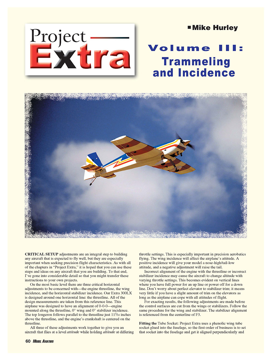
- To fit the tube horizontally, flip the fuselage on its back on a perfectly flat table and take measurements from the tabletop to the wingtips. If you do not have a perfect table, clamp a spare wing tube to the top of the fuselage and measure at the tips. Place the wings on the tube and use a long straight edge (we used an 8-foot piece of angle aluminum) to measure the wings.
- Make tiny adjustments by sanding the fuselage slightly to adjust the socket, remeasure until the horizontal angle is correct. Use a small wedge or toothpick to hold adjustments until you are ready to glue.
From 1/8-inch light plywood, make a pair of 3-inch-square tube-socket doublers with a 1.610-inch-diameter hole at the center. It may help to make the hole slightly undersized and sand it until you get a snug fit on the phenolic; the doublers need a tight fit. Box in the area where the doubler fits to the fuselage with two pieces of 3/8-inch square balsa.
Fit the socket into the fuselage with the doublers in place, square the tube to alignment using wedges, and do a final check. Tack-glue the socket to the fuselage with cyanoacrylate (CyA). Once satisfied with placement, final-glue the socket to the fuselage sides and slide the doublers over; glue them to the 3/8-inch balsa framework and the sides.
After the tube socket is finished, add the last diagonal brace into the fuselage.
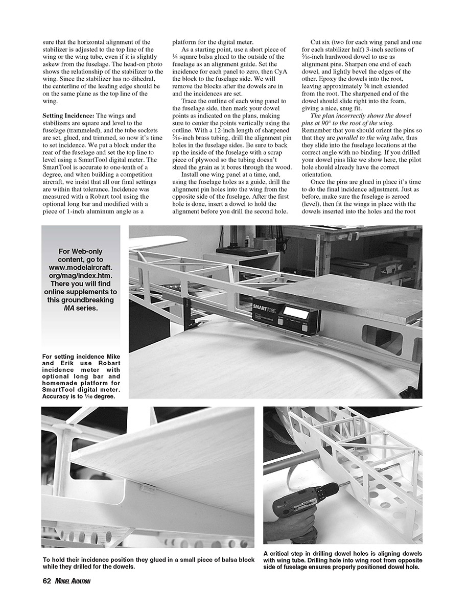
Follow the same procedure for the stabilizer tube socket, except it does not utilize an inside doubler. If a large adjustment is necessary to bring the tube into alignment, a circular doubler may be glued directly to the inside of the fuselage sides. Make sure that the horizontal alignment of the stabilizer is adjusted to the top line of the wing or the wing tube, even if it is slightly askew from the fuselage. Since the stabilizer has no dihedral, the centerline of the leading edge should be on the same plane as the top line of the wing.
Wing Alignment (Trammeling)
Next check the fore-and-aft alignment of the wings to ensure they are square to the fuselage centerline.
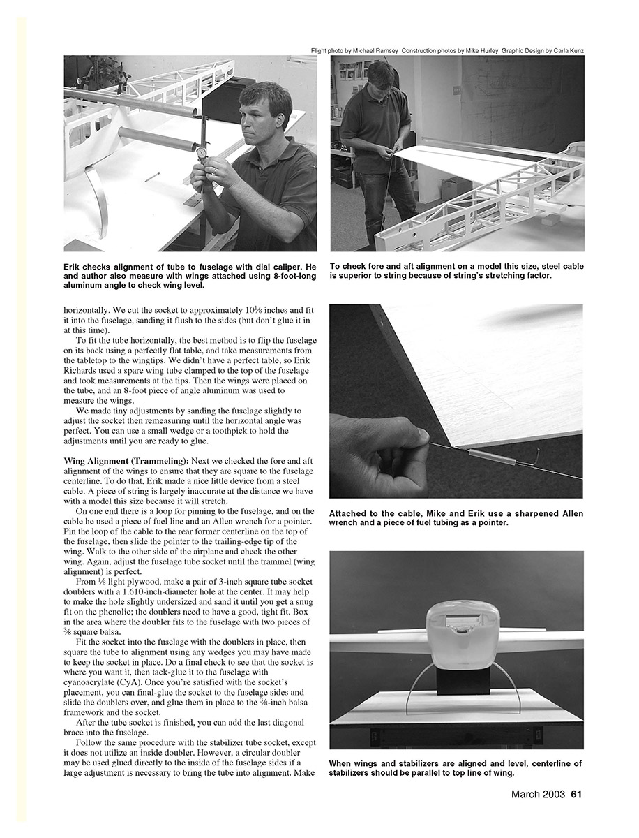
- Make a trammel device from a steel cable rather than string (string will stretch on a large model). Form a loop on one end for pinning to the fuselage. On the cable, add a piece of fuel line and an Allen wrench to act as a pointer.
- Pin the loop of the cable to the rear former centerline on the top of the fuselage, then slide the pointer to the trailing-edge tip of one wing. Walk to the other side and check the other wing. Adjust the fuselage tube socket until the trammel (wing alignment) is perfect.
Fit the socket into the fuselage with the doublers (as above) and square the tube to alignment using wedges. Do a final check, tack-glue, then final-glue when satisfied.
Setting Incidence
With the wings and stabilizers trammeled square and level to the fuselage and the tube sockets set, glued, and trimmed, set the incidence.
- Support the rear of the fuselage on a block and set the top line level using a digital meter (we used a SmartTool accurate to 0.1°). For competition aircraft, final settings should be within that tolerance.
- Incidence was measured with a Robart tool using the optional long bar and modified with a piece of 1-inch aluminum angle as a platform for the digital meter.
- As a starting point, glue a short piece of 1/4-inch square balsa to the outside of the fuselage as an alignment guide. Set the incidence for each panel to zero, then CyA the guide block to the fuselage side. Remove the blocks after the dowels are in and incidences are set.
Trace the outline of each wing panel on the fuselage side, then mark dowel points as indicated on the plans, centering the points vertically within the outline. With a 12-inch length of sharpened 5/16-inch brass tubing, drill the alignment pin holes in the fuselage sides. Back up the inside of the fuselage with scrap plywood so the tubing doesn't shred the grain as it bores through.
Install one wing panel at a time and, using the fuselage holes as a guide, drill the corresponding alignment pin holes into the wing from the opposite side of the fuselage. After drilling the first hole, insert a dowel to hold alignment before drilling the second.
Cut six 3-inch sections of 5/16-inch hardwood dowel (two for each wing panel and one for each stabilizer half). Sharpen one end of each dowel and lightly bevel the edges of the other. Epoxy the dowels into the root, leaving approximately 5/8 inch extended from the root. The sharpened end of the dowel should slide into the foam for a snug fit.
Note: The plan incorrectly shows the dowel pins at 90° to the wing root. Orient the pins so they are parallel to the wing tube; they must slide into the fuselage locations at the correct angle with no binding. If you drilled your pilot holes as described above, the orientation should be correct.
Final incidence adjustment:
- Make sure the fuselage is level.
- Fit the wings with the dowels inserted and the roots flush against the fuselage side.
- With a file or sandpaper, adjust the fuselage holes to obtain a zero reading on the SmartTool for both wings and the stabilizers.
It's acceptable to open up the holes if necessary, but try to keep the fit so you can hold the wing tight against one stop (up or down) with the meter at zero.
Cut four 1-1/2-inch-diameter light-plywood "doughnuts" with a 5/16-inch center hole that fits the dowels snugly to use as the final alignment setting (scrap from the fuselage lightening holes works well). With the wing held at zero, glue the doughnuts in place inside the fuselage over the pins, being careful not to get any glue on the dowels. Do the same for the stabilizer pins; those doughnuts can be roughly 1 inch in diameter.
Hatch and Turtledeck
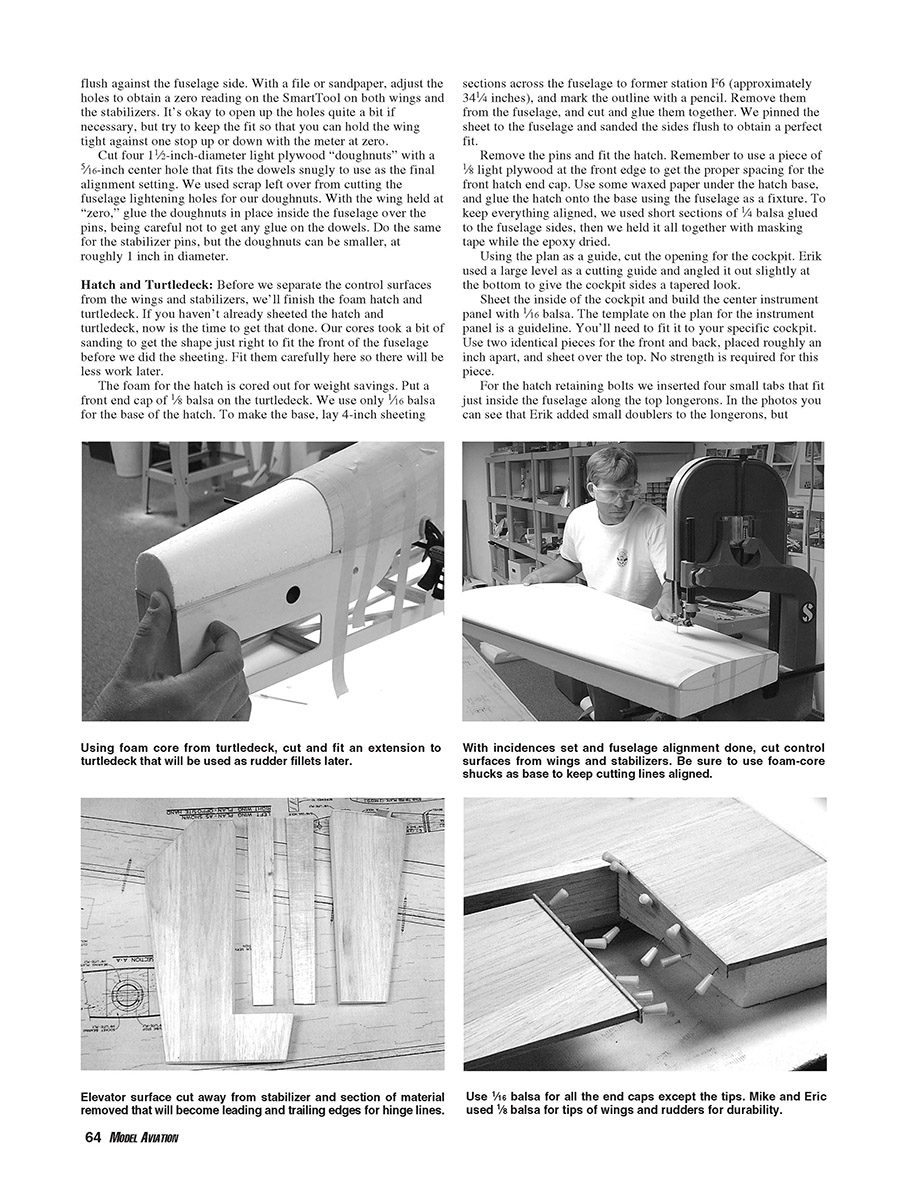
Before separating the control surfaces from the wings and stabilizers, finish the foam hatch and turtledeck. If you haven't already sheeted them, do so now. Fit them carefully—our cores required sanding to match the front of the fuselage before sheeting.
- The foam for the hatch is cored out for weight savings. Put a front end cap of 1/8-inch balsa on the turtledeck. Use 1/16-inch balsa for the base of the hatch.
- To make the base, lay 4-inch sheeting sections across the fuselage to former station F6 (approximately 3-1/4 inches) and mark the outline. Remove them, cut and glue them together, then pin the sheet to the fuselage and sand the sides flush for a perfect fit.
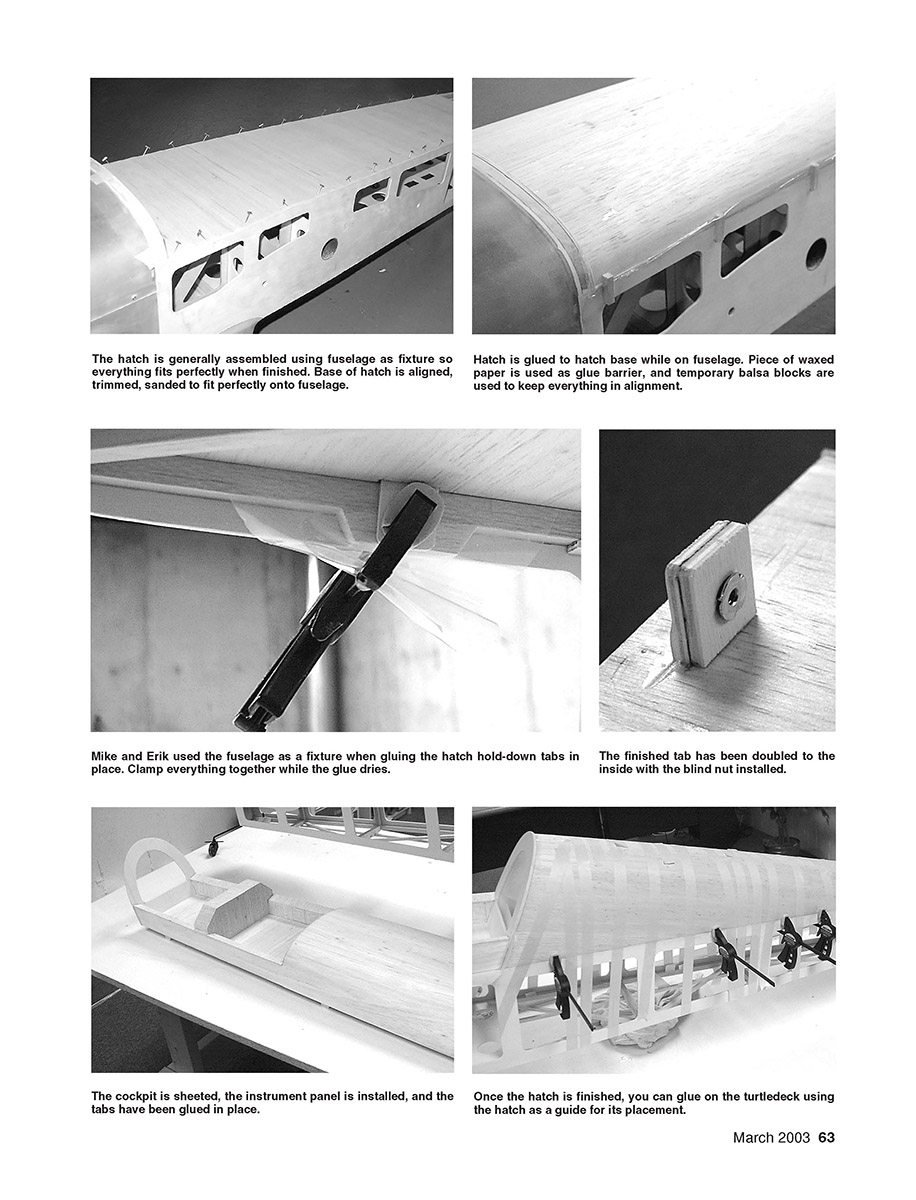
- Use a piece of 1/8-inch light plywood at the front edge for proper spacing of the front hatch end cap. Use waxed paper under the hatch base as a glue barrier, and glue the hatch onto the base using the fuselage as a fixture. To keep alignment, glue short sections of 1/4-inch balsa to the fuselage sides and hold everything with masking tape while the epoxy dries.
Cut the cockpit opening using the plan as a guide. We used a large level as a cutting guide and angled it slightly at the bottom to taper the cockpit sides.
Sheet the inside of the cockpit and build the center instrument panel from 1/16-inch balsa. The plan's template is a guideline; fit it to your cockpit. Use two identical panel pieces roughly an inch apart and sheet over the top—strength is not required for this piece.
For hatch retaining bolts, insert four small tabs that fit just inside the fuselage along the top longerons. Tape the hatch in place (use a dummy 1/8-inch light plywood piece at the front for spacing) and use an ink pad to stamp the tab locations. Cut the balsa away, slice the foam (do not remove it), sharpen one end of each tab to fit the slit in the foam, and epoxy the tabs into the hatch with waxed paper protecting the fuselage from excess glue. Clamp each tab while the epoxy dries for a snug fit.
When the tabs are set, double the tabs to the inside with scrap 1/8-inch light plywood. Re-place the hatch, drill through the fuselage and the hatch hold-down tabs, and install a 4-40 blind nut in each tab.
To cut the front end cap and the rear canopy former, trace the outline from the front of the hatch and the front of the turtledeck onto 1/8-inch light plywood. We opened our canopy former for weight savings, leaving 1 1/8 inches spacing around the top and 1 3/4 inches at the bottom. You may put lightening holes in the front end cap; we left ours solid. When gluing, use the turtledeck as a guide to get the canopy former angle correct. From the front side of F1, drill the 5/16-inch dowel holes into the hatch (see plan page 3, former F1A). Align the dowels while gluing with the hatch in place.
With the hatch in place and protected by waxed paper, glue the sheeted turtledeck to the fuselage. Tape it down and use clamps or balsa tabs to maintain alignment while the glue dries. After the glue has set, clean up the seam by block-sanding it smooth with a large "T" bar.
We used inner core scrap from the turtledeck to make a rudder fillet: cut and sand it to follow the turtledeck contour, then sheet it with leftover 1/16-inch balsa using spray-on contact cement. Set it aside for later.
Hinging and Control Surfaces
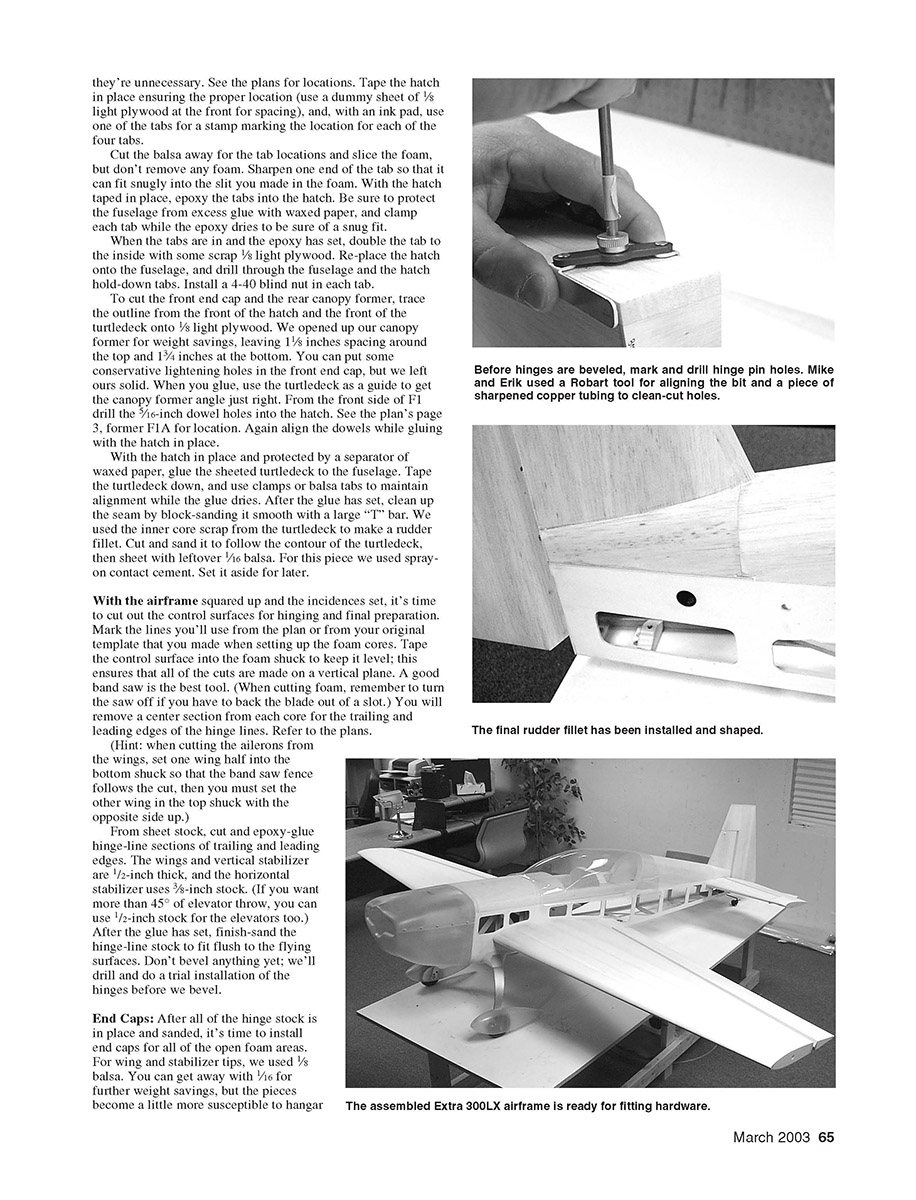
With the airframe squared and incidences set, cut out the control surfaces for hinging and final preparation.
- Mark the lines from the plan or your original template used when setting up the foam cores.
- Tape the control surface into the foam shuck to keep it level to ensure all cuts are on a vertical plane.
- A good band saw is the best tool. When cutting foam, turn the saw off if you have to back the blade out of a slot.
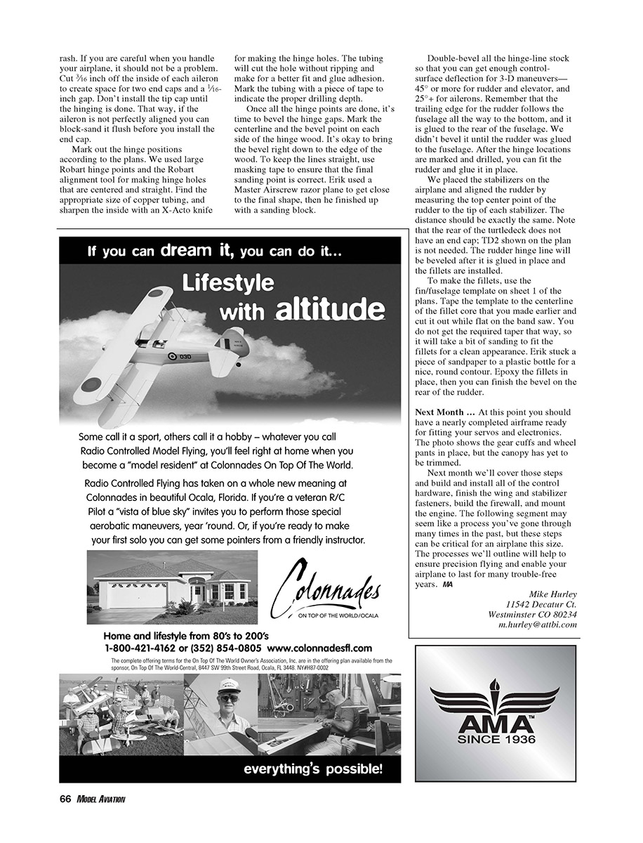
- Remove the center section from each core for the trailing- and leading-edge hinge lines. Refer to the plans for exact dimensions.
Hint: When cutting ailerons, set one wing half into the bottom shuck so the band saw fence follows the cut, then set the other wing in the top shuck with the opposite side up.
From sheet stock, cut and epoxy-glue hinge-line sections for trailing and leading edges. Wings and vertical stabilizer use 1/2-inch stock; the horizontal stabilizer uses 3/8-inch stock. If you want more than 45° of elevator throw, you can use 1/2-inch stock for the elevators too. After the glue sets, finish-sand the hinge-line stock to fit flush to the flying surfaces. Do not bevel yet; drill and do a trial installation of the hinges first.
End Caps
After hinge stock is in place and sanded, install end caps for all open foam areas.
- For wing and stabilizer tips, use 1/8-inch balsa. 1/16-inch can save weight but is more susceptible to damage.
- Install 1/8-inch balsa caps where z-bend and clevis hardware will be installed for added stiffness when drilling for bolts.
- Cut 3/16 inch off the inside of each aileron to create space for two end caps and a 1/16-inch gap. Do not install the tip cap until hinging is complete so you can sand the aileron flush if needed.
Mark hinge positions per the plans. We used large Robart hinge points and the Robart alignment tool to make centered, straight hinge holes. Use appropriate-size copper tubing and sharpen the inside with an X-Acto knife to cut hinge holes cleanly without ripping the foam. Mark the tubing with tape to indicate drilling depth.
Once hinge holes are done, bevel the hinge gaps:
- Mark centerline and bevel point on each side of the hinge wood.
- It's acceptable to bring the bevel right to the edge of the wood.
- Use masking tape to keep sanding lines straight.
- A razor plane gets you close; finish with a sanding block.
Double-bevel all hinge-line stock to enable sufficient control-surface deflection for 3-D maneuvers—45° or more for rudder and elevator, and 25°+ for ailerons.
The rudder trailing edge follows the fuselage to the bottom and is glued to the rear of the fuselage. We did not bevel it until the rudder was glued in place. After marking and drilling hinge locations, fit the rudder and glue it in place.
We placed the stabilizers on the airplane and aligned the rudder by measuring the top center point of the rudder to the tip of each stabilizer; these distances should match exactly. Note: the rear of the turtledeck does not require an end cap (TD2 on the plan is not needed). The rudder hinge line will be beveled after it is glued in place and the fillets are installed.
To make fillets, use the fin/fuselage template on sheet 1 of the plans. Tape the template to the centerline of the fillet core and cut it out flat on the band saw. The band saw cut will leave a uniform thickness, so expect to do sanding to achieve the required taper. Use a rounded sanding tool (we stuck sandpaper to a plastic bottle) for a nice contour. Epoxy the fillets in place, then finish the bevel on the rear of the rudder.
Next Month ...
At this point you should have a nearly completed airframe ready for fitting servos and electronics. The photos show the gear cuffs and wheel pants in place, but the canopy has yet to be trimmed.
Next month we'll cover those steps and build and install all control hardware, finish the wing and stabilizer fastenings, build the firewall, and mount the engine. Although the following steps may seem familiar, they are critical for an airplane of this size. The processes we'll outline will ensure precision flying and help your airplane last for many trouble-free years.
Mike Hurley 11542 Decatur Ct. Westminster, CO 80234 m.hurley@attbi.com
Transcribed from original scans by AI. Minor OCR errors may remain.

