
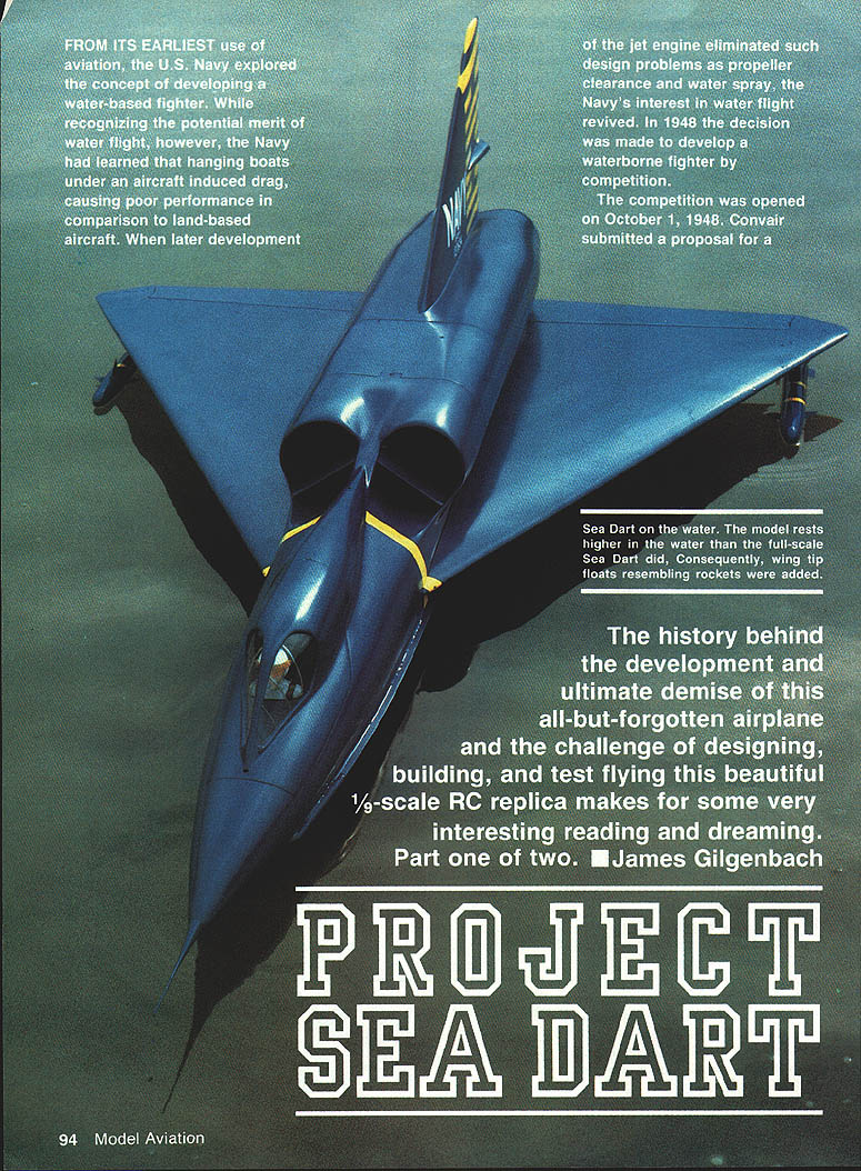
PROJECT SEA DART
From its earliest use of aviation, the U.S. Navy explored the concept of developing a water-based fighter. Early experience showed that hanging boats under an aircraft induced drag and gave poor performance compared with land-based aircraft. When jet engines eliminated propeller-clearance and water-spray problems, interest in water flight revived. In 1948 the Navy decided to develop a waterborne fighter by competition. The competition opened on October 1, 1948. Convair submitted a proposal for a swept-wing aircraft nicknamed the Skate because of its resemblance to a manta ray.
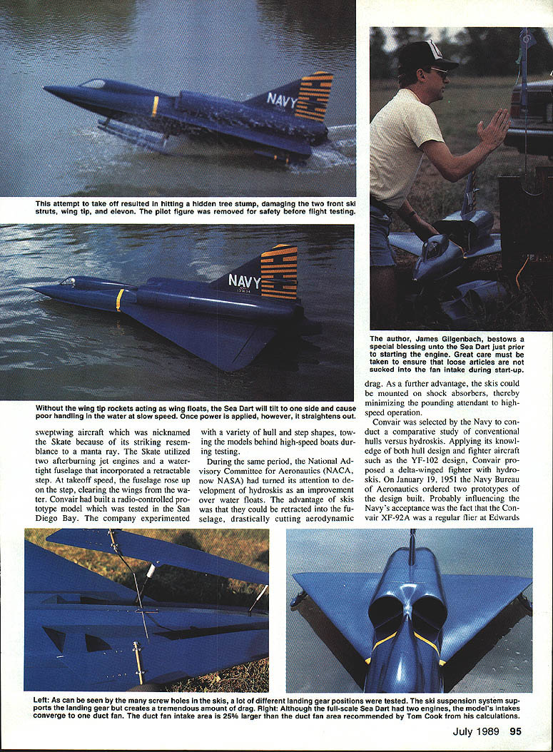
The Skate concept used two afterburning jet engines and a watertight fuselage with a retractable step. At takeoff speed the fuselage rose up on the step, clearing the wings from the water. Convair built a radio-controlled prototype model and tested it in San Diego Bay, experimenting with a variety of hull and step shapes by towing models behind high-speed boats.
During this period the National Advisory Committee for Aeronautics (NACA, now NASA) turned its attention to hydroskis as an improvement over floats. Skis could be retracted into the fuselage, drastically cutting aerodynamic drag, and could be mounted on shock absorbers to reduce pounding at high speeds.
Convair was selected by the Navy to conduct a comparative study of conventional hulls versus hydroskis. Applying hull knowledge from fighters such as the YF-102, Convair proposed a delta-winged fighter with hydroskis. On January 19, 1951 the Navy Bureau of Aeronautics ordered two prototypes. Convair’s experience with the XF-92A at Edwards AFB probably helped the proposal’s acceptance.
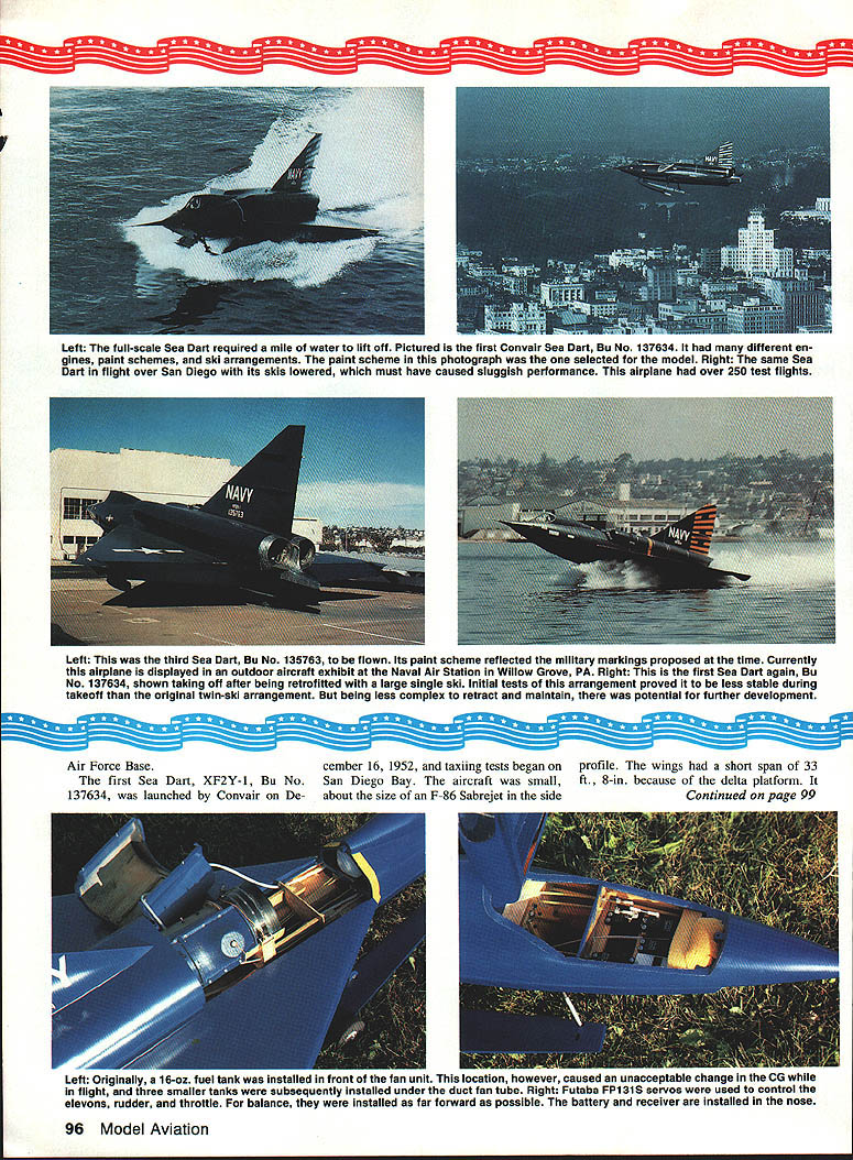
The first Sea Dart, XF2Y-1 Bu. No. 137634, was launched by Convair on December 16, 1952 and began taxiing tests in San Diego Bay. The aircraft was compact—its short-span delta wings measured 33 ft. 8 in., and its profile was similar in size to the F-86 Sabrejet. Early powerplants were two Westinghouse J34-WE-42 turbojets delivering about 3,400 lb static thrust each; gross weight during initial tests was about 16,527 lb.
During water-taxi tests it became clear the hydroskis needed development. Above about 60 mph the twin skis pounded against waves, subjecting the pilot and airframe to severe shaking. Takeoff speeds of at least 140 mph were unacceptable. Convair tested numerous ski modifications (over a hundred variations) through mid‑1954.
After modifications, test pilot Sam Shannon made the first official flight on August 9, 1953. Once airborne the Sea Dart handled much like other high-performance jets of the era.
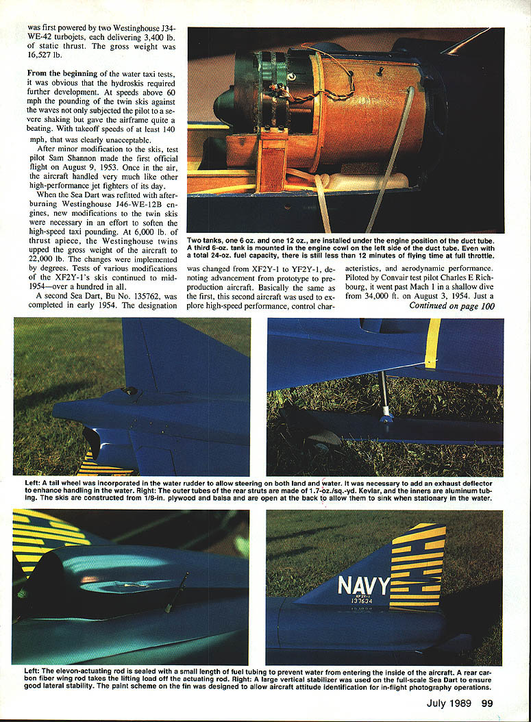
The Sea Dart was later refitted with afterburning Westinghouse J46-WE-12B engines producing roughly 6,000 lb thrust each; the twin J46s increased gross weight to about 22,000 lb. These changes improved performance and addressed some earlier handling and structural problems.
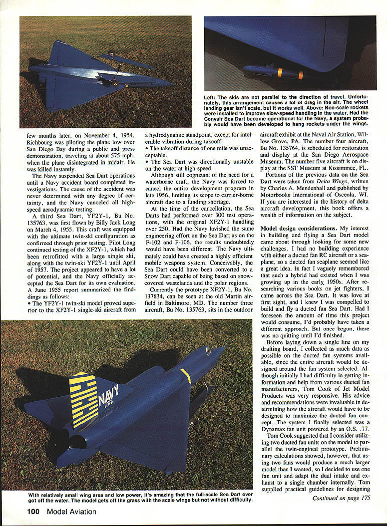
A second Sea Dart, Bu. No. 135762, was completed in early 1954 and redesignated from XF2Y-1 to YF2Y-1, indicating advancement from prototype to preproduction. Piloted by Convair test pilot Charles E. Richburg, it exceeded Mach 1 in a shallow dive from 34,000 ft on August 3, 1954. On November 4, 1954, while flying low over San Diego Bay at about 575 mph during a public demonstration, Richburg’s aircraft disintegrated in midair and he was killed instantly. The Navy suspended Sea Dart operations while an accident board investigated; the cause was never determined with certainty, and the Navy canceled all high-speed aerodynamic testing.
A third Sea Dart, YF2Y-1 Bu. No. 135763, was first flown by Billy Jack Long on March 4, 1955. This aircraft incorporated the improved twin-ski configuration developed through prior testing. Long continued testing the modified single-ski XFY2Y-1 and the twin-ski YF2Y-1 through April 1957. The Navy officially accepted the Sea Dart for evaluation.
A June 1955 report summarized findings:
- The YF2Y-1 twin-ski model was hydrodynamically superior to the single-ski XFY2Y-1, except for intolerable vibration during takeoff.
- The takeoff distance (about one mile) was unacceptable.
- The Sea Dart was directionally unstable on the water at high speed.
Although the project showed promise, the Navy canceled the entire development program in late 1956 (limiting future effort to carrier‑borne aircraft) largely due to funding shortages. Nevertheless, Sea Darts completed over 300 test operations; the original XF2Y-1 performed over 250 of these.
Had the Navy invested effort comparable to that devoted to the F-102 and F-106, the Sea Dart might have matured into an efficient, mobile weapons system—and conceivably could have been adapted for other environments (for example, as a "Snow Dart" for snow‑covered regions).
Surviving airframes and display locations:
- XF2Y-1, Bu. No. 137634: old Martin airfield, Baltimore, MD.
- YF2Y-1 (number three), Bu. No. 135763: outdoor aircraft exhibit, Naval Air Station Willow Grove, PA.
- Bu. No. 135764 (number four): scheduled for restoration and display at the San Diego Aerospace Museum.
- Number five aircraft: on display at the SST Museum, Kissimmee, FL.
Portions of this account are drawn from Delta Wings by Charles A. Mendenhall (Motorbooks International).
Model design considerations
My interest in building and flying a Sea Dart model came from wanting new challenges: I had no previous experience with ducted-fan RC aircraft or seaplanes, so a ducted-fan seaplane appealed to me. After researching various jet-fighter books I discovered the Sea Dart and decided to build a 1/9-scale ducted-fan model.
Before drawing plans I collected data on available ducted-fan systems because the airframe design and weight distribution would center on the fan chosen. Tom Cook of Jet Model Products provided invaluable advice. I selected a Dynamax fan unit powered by an O.S. .77 engine. Tom suggested considering two ducted fans to mirror the full-scale twin engines, but preliminary calculations showed two fans would make the model much larger than I wanted. I therefore used a single fan and adapted the twin intake/exhaust arrangement to a single internal chamber. Tom also provided practical guidelines for the fan intake and exhaust; I focused on maximizing static thrust for water takeoff.
Design and equipment choices:
- Fuel tank: originally a single 16‑oz tank forward of the fan caused an unacceptable forward shift in center of gravity; I replaced it with three smaller tanks under the duct fan tube.
- Servos: Futaba FP-131S servos controlled the elevons, rudder, and throttle.
- Radio: selected Futaba Conquest PCM system for its interference rejection, dual rates, servo reversing, waterproof servos, and excellent range. Antenna was buried inside the fuselage.
- Balance: installed weight as far forward as possible; battery and receiver were placed in the nose.
- Materials: used composites where strength was required and balsa for non‑stress areas to keep weight low.
- Waterproofing: continually monitored added weight from epoxy and paint; discarded overly heavy components and rebuilt lighter ones as needed.
Early in the process I decided to rotate the engine and fan unit to allow full cowling access and hatch removal. This required a new mounting method: the fan unit was strapped in a cradle using silicone sealer as a shock absorber, which proved effective.
Weight and wing considerations:
- Target finished weight: about 10 lb.
- Calculated wing loading: 22.5 oz./sq. ft. overall; because a flying wing uses about 75% of its area for lift (25% acting as horizontal stabilizer), effective wing loading rose to about 30.0 oz./sq. ft.
- To allow flexibility, I made the wings detachable so larger wings could be substituted if needed.
Water handling: because the full-scale Sea Dart had directional control problems on water, I designed a water rudder and exhaust deflector for the model, which proved useful.
Building the model required more hours than previous sport and pattern aircraft I had built. Concerned about radio failure destroying the project, I prioritized reliability in the radio and servos.
Composite material techniques
The exhaust tube was the first composite item I made. After several attempts I settled on a tube made from 1.7‑oz./sq.‑yd. woven Kevlar and blueprint paper. The technique:
- Tape freezer paper to a flat surface, then tape waxed paper over the freezer paper and blueprint paper over the waxed paper.
- Cut a piece of 1.7‑oz./sq.‑yd. woven Kevlar slightly larger than the finished tube and lay it over the blueprint paper.
- Mix epoxy and brush a thin coat over the blueprint paper, then lay the Kevlar onto the wet epoxy and wet it out thoroughly.
- Lay a sheet of waxed paper over the Kevlar and roll a dowel or squeegee over the layup to remove excess resin.
- Allow the layup to cure, then peel off the waxed paper and freezer paper; the blueprint paper acts as a release and is removed next to reveal a smooth Kevlar tube.
Transcribed from original scans by AI. Minor OCR errors may remain.

