
PROJECT SEA DART
In Part 1 the development and ultimate demise of the Convair Sea Dart was traced, along with some construction notes pertaining to this magnificent model. Part 2 this month concludes with a further description of construction techniques and a discussion of the model's first test flights, evaluations, modifications, and reevaluations. — James Gilgenbach
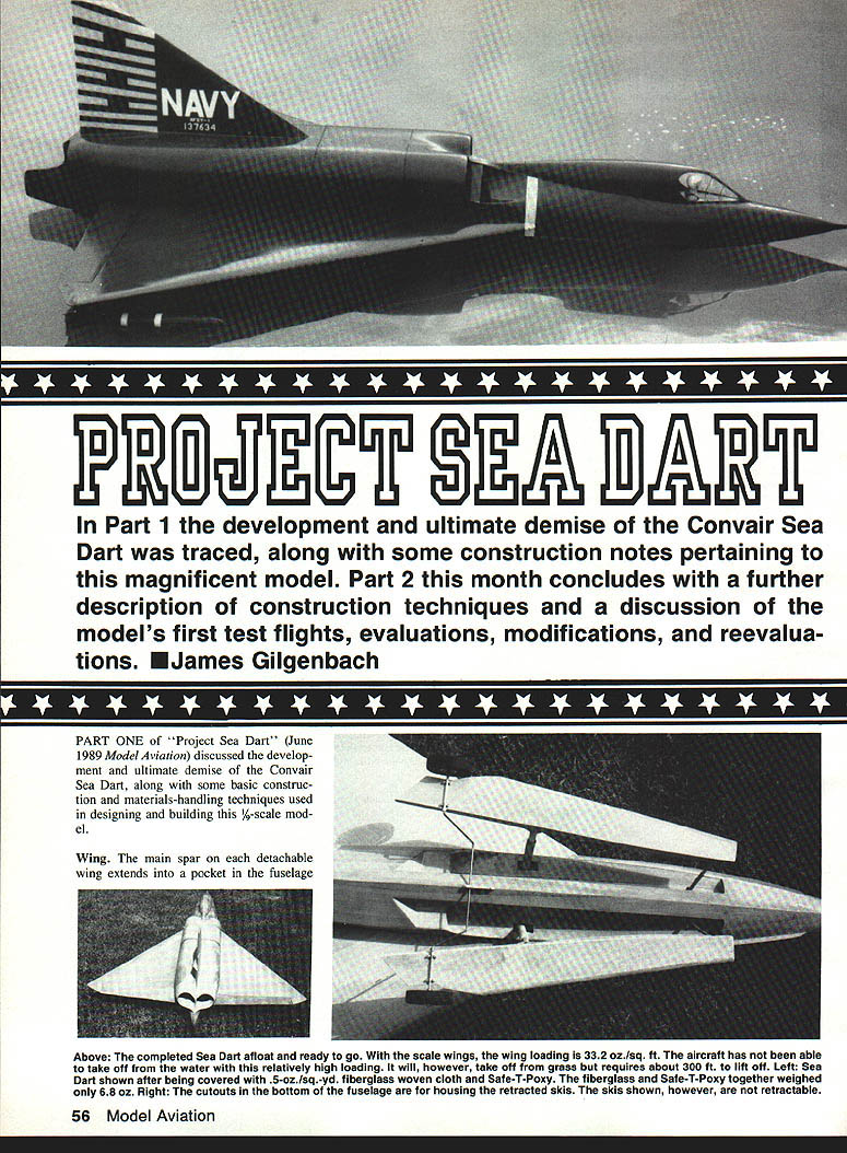
PART ONE of "Project Sea Dart" (June 1989 Model Aviation) discussed the development and ultimate demise of the Convair Sea Dart, along with some basic construction and materials-handling techniques used in designing and building this 1/6-scale model.
Wing
The main spar on each detachable wing extends into a pocket in the fuselage and carries most of the lifting load. It was made by laminating a 0.014-in.-thick unidirectional carbon fiber laminate between two pieces of 1/16-in. plywood, then capping the edges of this assembly with 0.014-in.-thick by 1/2-in.-wide carbon fiber laminate. Zap-A-Gap or Slo-Zap works best for gluing the carbon fiber. The carbon fiber should be sanded smooth on the smooth side to ensure a good bond. Balsa caps were placed between the ribs on top of the main spar and sanded to match the wing contour.
The wing skin, or sheeting, is made by laminating 0.25-oz./sq.-yd. Kevlar mat to 3/32-in. contest balsa sheeting. Here's the best method I've found:
- Using a straightedge, trim the edges of the 3/32-in. balsa, then tape the balsa sheets together with Scotch (Magic Transparent type) tape for the full length of the joint.
- Cover the work surface with waxed paper and freezer wrap, then place the balsa sheeting, tape side down, on top of it.
- Lay the Kevlar mat over the balsa and spread Safe-T-Poxy, thinned 50% with denatured alcohol, over the Kevlar.
- With a printer's roller, squeegee the Safe-T-Poxy evenly over the Kevlar and balsa. Be careful not to roll up the Kevlar onto the roller.
- Place waxed paper over the Kevlar. Put a large sheet of glass over the waxed paper and weigh it down for 24 hours.
- Remove the Scotch tape, and flat sand the seams.
You now have a strong wing skin that weighs a mere 0.0035 oz./sq. in. and is waterproofed on the inside with Safe-T-Poxy and Kevlar.
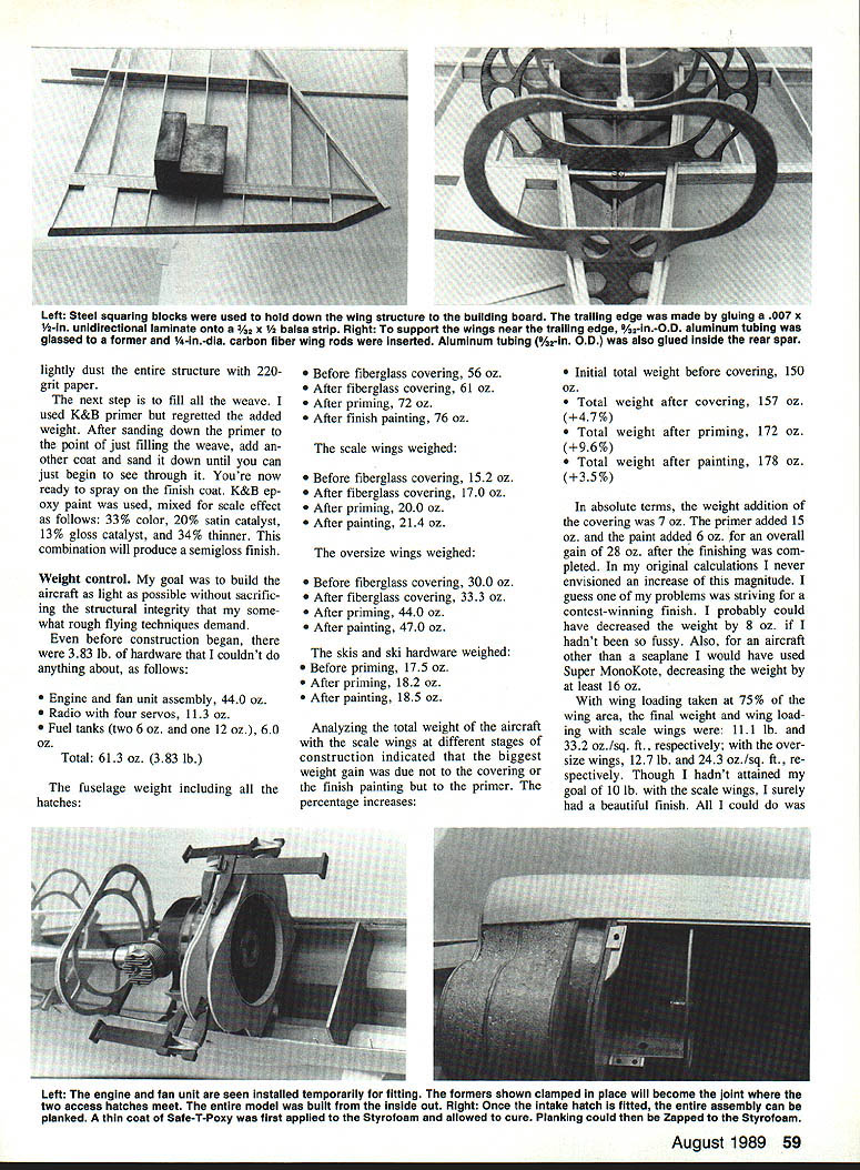
The rear spar is made by laminating a 0.014-in. x 1/4-in. unidirectional carbon fiber laminate strip to a 3/32-in. x 1/4-in. balsa stick. Make up two of these strips, top and bottom, glue them to a 1/4-in.-sq. balsa stick with the carbon fiber between. A 3/32-in.-dia. aluminum tube is also glued between the two strips and accepts a 1/4-in.-dia. carbon fiber wing rod for attachment to the fuselage. The aluminum tube is boxed in on the sides with 0.014-in. carbon fiber and balsa.
Make the trailing edge by gluing a 0.007-in. x 1/16-in. unidirectional carbon fiber laminate onto a 3/32-in. x 1/4-in. balsa strip. This makes a light, strong trailing edge that can be sanded to a sharp contour.
Landing Gear Strut
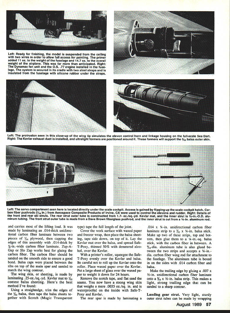
Very light, sturdy outer strut tubes can be made by wrapping 7-oz./sq.-yd. woven Kevlar thoroughly wetted with Safe-T-Poxy around the inner strut leg. Wrapping waxed paper around the outside assembly ensures roundness and minimizes final sanding.
Landing gear areas, wing-rod tubes and fuselage are reinforced by cutting appropriate size pieces of 1.7-oz. Kevlar, soaking them with Safe-T-Poxy and working them in place.
Pushrods
Aerospace Composite Products in Irvine, CA supplies a 1/16-in. dia. carbon fiber rod that works great for pushrods when run through the inside of a yellow inner Gold-N-Rod. A straight shot from servo to control horn is necessary, as the rod can't be bent very much. The Gold-N-Rod must be glued to the formers to avoid flexing of the pushrod assembly.
To attach a Kwik Link, rough up the end of the 1/16-in. carbon fiber rod, clean the Kwik Link with denatured alcohol, then apply Zap-A-Gap onto the rod end and slide the Kwik Link over it. When this is dry, wrap carbon fiber ribbon around the rod and Kwik Link, then Zap in place.
A threaded end can be attached the same way. However, if you want to make it detachable, first file a notch in the tube portion of the threaded end and slide in the rod. Put a wheel collar over the end, and, using a socket head cap screw in the collar rather than the setscrew that comes with it, clamp the rod through the notch. The cap screw is smooth on the end and won't cut through the carbon fibers.
Intake and Exhaust Ducts
After making the intake and exhaust ducts from balsa, plywood, and Styrofoam, cut out pieces of 1.7-oz. Kevlar to match. Cover the structure inside and out with the Kevlar, just as you would using fiberglass. Brush on Hobbypoxy II, mixed 50/50 with microballoons, thoroughly soaking it through the Kevlar. Kevlar doesn't sand well, so be sure to keep all the ends and edges as flat as possible and covered with the epoxy mix. Sand as smooth as possible when dry, then apply another coat of the mix. Repeat this procedure until you have a completely smooth surface.
Formers
The load-bearing formers that support the landing gear and engine cradle were made by laminating 1.7-oz. woven Kevlar to the outside of 1/8-in. Lite Ply, then laminating 1/4-in. plywood on both sides of the assembly using Safe-T-Poxy. After laminating, the entire assembly was weighted down for 24 hours.
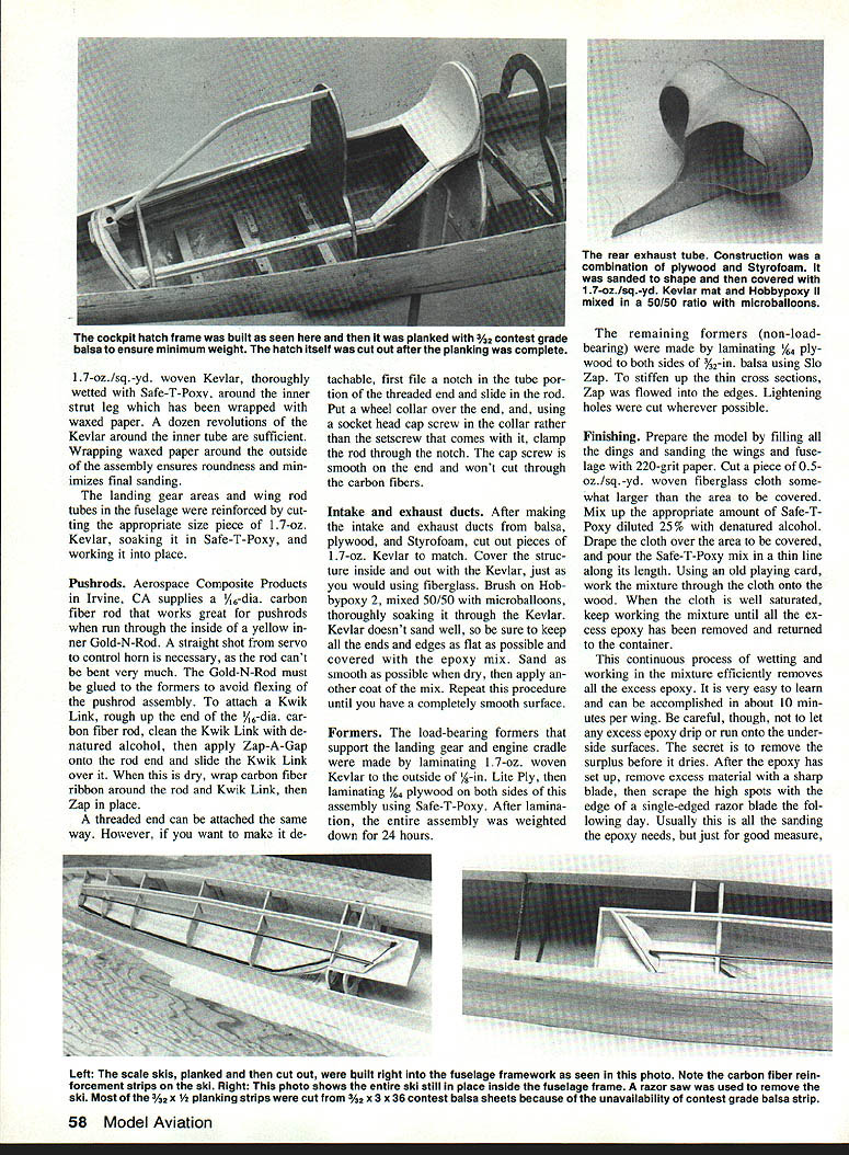
The rear exhaust tube construction was a combination of plywood and Styrofoam. It was sanded to shape and then covered with 1.7-oz./sq.-yd. Kevlar mat and Hobbypoxy II mixed in a 50/50 ratio with microballoons.
The remaining formers (non-load-bearing) were made by laminating 1/32-in. plywood to both sides of 3/32-in. balsa using Slo-Zap. To stiffen up the thin cross sections, Zap was flowed into the edges. Lightening holes were cut wherever possible.
Finishing
Prepare the model by filling all the dings and sanding the wings and fuselage with 220-grit paper. Cut a piece of 0.5-oz./sq.-yd. woven fiberglass cloth somewhat larger than the area to be covered. Mix up the appropriate amount of Safe-T-Poxy diluted 25% with denatured alcohol. Drape the cloth over the area to be covered, and pour the Safe-T-Poxy mix in a thin line along its length. Using an old playing card, work the mixture through the cloth onto the wood. When the cloth is well saturated, keep working the mixture until all the excess epoxy has been removed and returned to the container.
This continuous process of wetting and working in the mixture efficiently removes all the excess epoxy. It is very easy to learn and can be accomplished in about 10 minutes per wing. Be careful, though, not to let any excess epoxy drip or run onto the undersurfaces. The secret is to remove surplus before it dries. After the epoxy has set up, remove excess material with a sharp knife, then scrape the high spots with the edge of a single-edged razor blade the following day. Usually this is all the sanding the epoxy needs, but just for good measure, lightly dust the entire structure with 220-grit paper.
The next step is to fill all the weave. I used K&B primer but regretted the added weight. After sanding down the primer to the point of just filling the weave, add another coat and sand it down until you can just begin to see through it. You're now ready to spray on the finish coat. K&B epoxy paint was used, mixed for scale effect as follows: 33% color, 20% satin catalyst, 13% gloss catalyst, and 34% thinner. This combination will produce a semigloss finish.
Weight Control
My goal was to build the aircraft as light as possible without sacrificing the structural integrity that my somewhat rough flying techniques demand.
Even before construction began, there were 3.83 lb. of hardware that I couldn't do anything about, as follows:
- Engine and fan unit assembly: 44.0 oz.
- Radio with four servos: 11.3 oz.
- Fuel tanks (two small and one 12-oz.): 6.0 oz.
Total: 61.3 oz. (3.83 lb.)
The fuselage weight including all the hatches:
- Before fiberglass covering: 56 oz.
- After fiberglass covering: 61 oz.
- After priming: 72 oz.
- After finish painting: 76 oz.
The scale wings weighed:
- Before fiberglass covering: 15.2 oz.
- After fiberglass covering: 17.0 oz.
- After priming: 20.0 oz.
- After painting: 21.4 oz.
The oversize wings weighed:
- Before fiberglass covering: 30.0 oz.
- After fiberglass covering: 33.3 oz.
- After priming: 44.0 oz.
- After painting: 47.0 oz.
The skis and ski hardware weighed:
- Before priming: 17.5 oz.
- After priming: 18.2 oz.
- After painting: 18.5 oz.
Analyzing the total weight of the aircraft with the scale wings at different stages of construction indicated that the biggest weight gain was due not to the covering or the finish painting but to the primer. The percentage increases:
- Initial total weight before covering: 150 oz.
- Total weight after covering: 157 oz. (+4.7%)
- Total weight after priming: 172 oz. (+9.6%)
- Total weight after painting: 178 oz. (+3.5%)
In absolute terms, the weight addition of the covering was 7 oz. The primer added 15 oz. and the paint added 6 oz. for an overall gain of 28 oz. after the finishing was completed. In my original calculations I never envisioned an increase of this magnitude. I guess one of my problems was striving for a contest-winning finish. I probably could have decreased the weight by 8 oz. if I hadn't been so fussy. Also, for an aircraft other than a seaplane I would have used Super MonoKote, decreasing the weight by at least 16 oz.
With wing loading taken at 75% of the wing area, the final weight and wing loading with scale wings were: 11.1 lb. and 33.2 oz./sq. ft., respectively; with the oversize wings, 12.7 lb. and 24.3 oz./sq. ft., respectively. Though I hadn't attained my goal of 10 lb. with the scale wings, I surely had a beautiful finish. All I could do was test fly the aircraft and see what would happen.
TESTING
Engine and Fan
The first test was to determine how well the engine and fan unit would perform in the aircraft. I had two concerns. I was worried that the engine might not properly draw the fuel from the lower two tanks located below the fan unit (I did not want to use a pump). I also thought my fan mounting method might cause excessive vibration.
I quickly discovered that the engine had so much compression, especially with a little oil in the cylinder, that a standard electric starter wouldn't even turn it over. I loosened up the glow plug slightly to release the compression, and cranked the engine over with the electric starter. Just as I had feared, the engine didn't draw enough fuel to start, but priming it through the fuel inlet line started it almost immediately.
Once the oil was burned out and the engine warmed up slightly, I stopped it and tightened the plug. Though the engine would run over the starter, it still wouldn't draw enough fuel to restart. I primed it again, and, just as before, it started immediately. Obviously, I'd have to design a better way to prime the engine.
After the engine was reasonably warmed up, I gave it full throttle, adjusted the high-speed needle valve for peak rpm, then richened it out about two clicks. The O.S. .77 with an O.S. No. 8 plug was turning the Dynamax fan at 21,000 rpm, and the vibration level was within tolerance. Holding the plane at different attitudes had no effect on the engine rpm, and the idle was flawless. Unlike the first, this portion of the testing was an unequivocal success.
Water Test
The first water taxiing tests revealed two unexpected problems. First, with the scale wings the model sat much higher in the water than had the full-size aircraft, causing it to tip to one side and immerse the wing tip. This resulted in poor taxiing characteristics. Second, water was somehow getting into the fuselage. Further analysis showed that it was entering through the hatch seams. To solve the first problem, I built scale rockets and mounted them onto the wing tips to act as pontoons. To stop the leaks, I sealed the hatch seams with silicone sealer, using Liquid Masking as a release agent on the hatches.
The second water taxiing test was very successful. With the combination water rudder and exhaust deflector connected to the air rudder, the model turned in the water on command.
High-Speed Water Taxiing Test
The moment of truth was quickly approaching, and I couldn't resist giving the model full throttle to see what would happen. To my amazement, the Sea Dart lifted gracefully out of the water on its skis and went on-plane while still picking up speed. As the airplane reached what I considered a reasonable takeoff speed, I introduced about 50% up elevator. Nothing happened! I tried full up elevator, and still nothing happened. The model, oblivious to my commands, continued skimming across the water like a hydroplane. Then, with a sudden swerve it drastically changed course and flipped unceremoniously onto the shore.
Investigation showed that the two front ski struts were broken and the right wing was smashed on the end. Apparently I had hit a stump sticking slightly out of the water.
A week later, after implementing repairs and moving the radio battery pack from the nose to the tail, I was ready to resume testing. Feeling that I was very close to success, I had several friends with 35mm and video cameras on hand to record the momentous occasion. I taxied the model out well away from all the stumps, aimed it into the wind, and gave it full throttle. It rose up on the skis very quickly, but the tail still dragged in the water—and didn't respond to full down elevator by lifting. After a dozen valiant attempts to get it on-plane and into the air, I finally conceded defeat and docked it for the day.
Flying Test
With the weather turning colder, I could no longer persuade my daughter to fly and retrieve the Sea Dart from the water. I resorted to putting a land gear under the skis and attempting takeoff from land.
On a cold, windy Thursday evening our Fond du Lac Miniature Aircraft Association (FMAA) members gathered at the local flying field for one of our monthly fly-in and meeting nights. After helping my helpers, I fired up and taxied the Sea Dart into position. Heading the model directly into the wind, I gave it full throttle. It quickly jumped into the air, but proved difficult to hold full up elevator just to stay aloft—an unexpected predicament that threw me on the verge of panic. Should I abort? Where will I land? Will it continue to fly? Ultimately it was the consistent screaming sound of the O.S. .77 and the positive feel of the Futaba PCM that gave me the confidence to continue.
The model was now gaining altitude with full up elevator. Nursing it upwind as far as I could see, I slowly started a gentle left-hand turn—and the airplane maintained altitude. By then my assistant, Gus Rebenburg, was able to give me full up trim while I held full up elevator, and the model began climbing like mad. I leveled off at approximately 200 ft. of altitude and analyzed the airplane's flight characteristics and idiosyncrasies. Knowing that a detailed stick landing would probably be disastrous, I decided to give the amount of up elevator required to maintain level flight and to attempt a first landing. With Gus' assistance, I set up for the landing, tucked over throttle to approximately one-third, and watched the Sea Dart settle in for an almost picture-perfect return to Earth.
Having concluded from the first flight that the model was tail nose-heavy, I recalculated the center-of-gravity and added 6 oz. of weight to the tail. With that accomplished, I felt secure enough in the reliability of the O.S. .77 engine, Dynamax fan, and Futaba PCM radio to do the next test flight at the Brillion Fun-Fly. With only a light breeze and Brillion's relatively small field, I'm sure quite a few bets were placed on whether I'd get the Dart airborne—or end up in the swamp grass. I asked Bob Johnson, a friend and vice president of the FMAA, to videotape the flight.
On the first takeoff attempt the Sea Dart was heading toward the pits, so I aborted. After realigning my takeoff direction, I again applied full throttle and the Dart traveled about 300 ft. to the edge of the field before lifting off. As she lofted over the marsh, the wings rocked ominously and she seemed close to faltering. For a moment there I could picture the Sea Dart mockingly rechristened the "Swamp Dart," sinking into notoriety among other models-that-didn't-quite-make-it, forever after the butt of ridicule.
However, again with full up elevator, the Dart straightened and began slowly gaining altitude. Once she'd attained full speed, only a slight amount of up trim was necessary. But the airplane still was sluggish and lacked good vertical performance. The open ski wells, skis, extra landing gear, and wheels seemed to be acting as giant air brakes. At least I had the consolation of knowing that with all the modifications of the full-size Dart, it, too, must have made many flights in which unretracted skis retarded the speed.
The landing was uneventful. All I had to do was pull back to one-third throttle and flare it in.
As the test results make clear, I'll need to introduce several modifications and conduct additional tests in order to optimize the Sea Dart's performance. My plan for implementing and testing the changes is as follows:
- Modification: Install larger wings.
- Tests:
- Attempt takeoff from snow.
- Attempt takeoff from water.
- Modification: Remove skis, cover ski wells, add wheels.
- Tests:
- Attempt takeoff from grass with scale and large wings.
- Analyze high-speed performance with scale and large wings.
If the test results are positive and the model gains the hoped-for agility, I intend to add retractable skis. Perhaps it is fitting that this Scale edition of the Convair Sea Dart is still in transition. The full-size seaplane was itself halted in an experimental stage when the Navy ran short of funding. At any rate, especially with the retractable hydroskis, the Sea Dart model promises to meld authenticity with the best performance attainable. That's going to keep me busy for some time.
Transcribed from original scans by AI. Minor OCR errors may remain.

