
Propeller Power and Efficiency
There's a lot that can be learned from this article and the nomograph. Give it a try. ■ John Brownlee
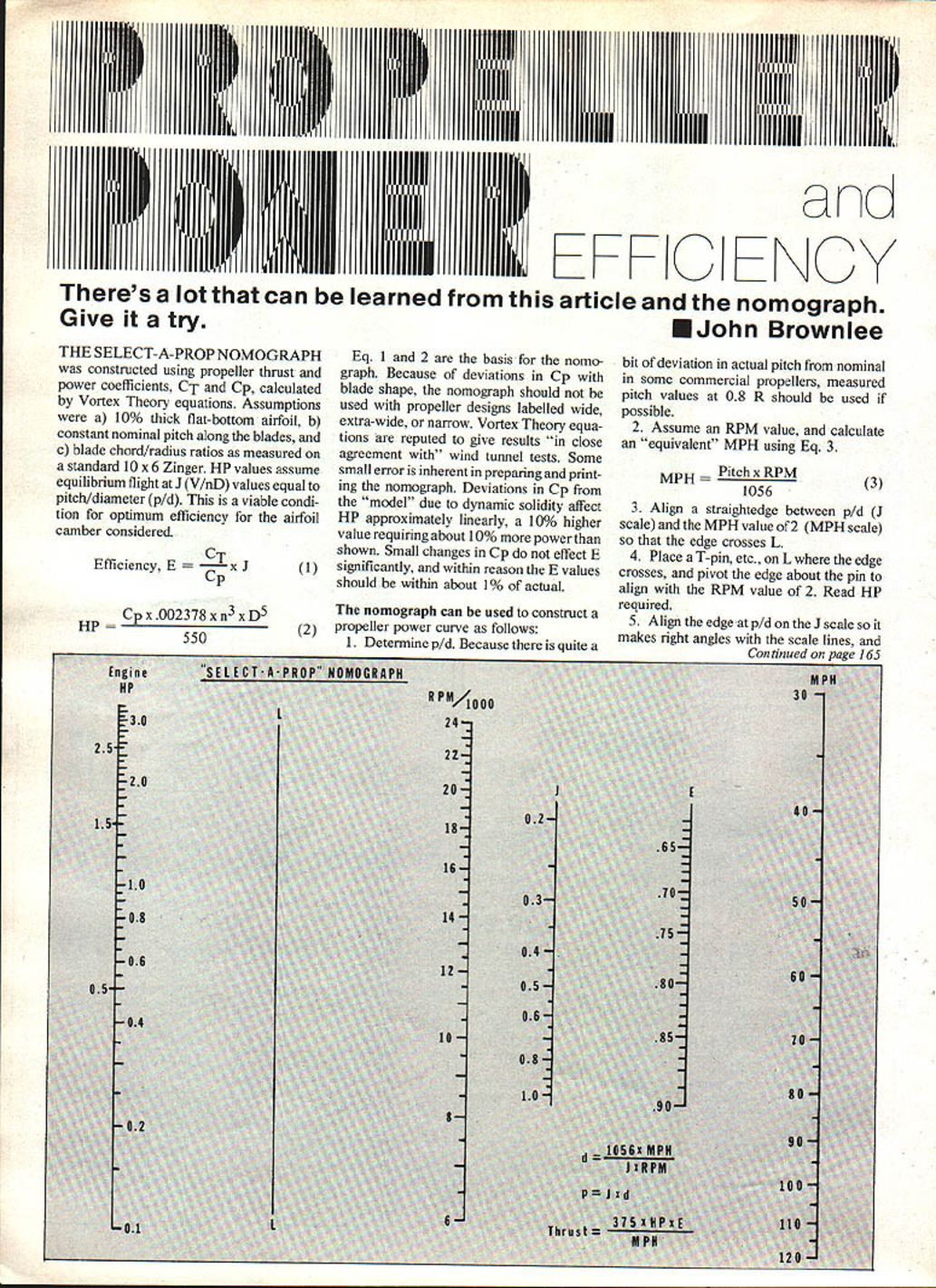
The Select-A-Prop Nomograph
The Select-A-Prop nomograph was constructed using propeller thrust and power coefficients, CT and CP, calculated by Vortex Theory equations. Assumptions were:
- 10% thick flat-bottom airfoil,
- constant nominal pitch along the blades, and
- blade chord/radius ratios as measured on a standard 10 x 6 Zinger.
HP values assume equilibrium flight at J (V/nD) values equal to pitch/diameter (p/d). This is a viable condition for optimum efficiency for the airfoil camber considered.
Efficiency: E = CT / CP × J (1)
Power (HP): HP = CP × 0.002378 × n^3 × D^5 / 550 (2)
Equations 1 and 2 are the basis for the nomograph. Because of deviations in CP with blade shape, the nomograph should not be used with propeller designs labeled wide, extra-wide, or narrow. Vortex Theory equations are reputed to give results "in close agreement with" wind tunnel tests. Some small error is inherent in preparing and printing the nomograph.
Deviations in CP from the "model" due to dynamic solidity affect HP approximately linearly: a 10% higher CP requires about 10% more power than shown. Small changes in CP do not affect E significantly; within reason the E values should be within about 1% of actual.
Using the Nomograph to Construct a Propeller Power Curve
- Determine p/d. Because there is quite a bit of deviation in actual pitch from nominal in some commercial propellers, measured pitch values at 0.8R should be used if possible.
- Assume an RPM value, and calculate an "equivalent" MPH using:
MPH = Pitch × RPM / 1056 (3)
- Align a straightedge between p/d (J scale) and the MPH value on the MPH scale so that the edge crosses L (on the nomograph).
- Place a T‑pin, etc., on L where the edge crosses, and pivot the edge about the pin to align with the RPM value. Read HP required.
- Align the edge at p/d on the J scale so it makes right angles with the scale lines.
Read E from the E scale. Calculate thrust as shown on the nomograph.
As pure calculations, the errors in HP and thrust will be the total inherent in the nomograph plus any deviation in CP of the propeller considered from the "model" used. In a practical sense, these errors can be reduced substantially if an accurate engine power curve is used in conjunction with the calculations. Continue steps 2, 3, and 4 until the propeller power curve intersects the engine power curve. You may also use the cube law after the initial estimate. For optimum power usage, the intersection of the curves should be near the peak power RPM of the engine where the curve is relatively flat.
If the CP of the propeller measured is, say, 10% higher than the model, the result will be that the engine will turn about 3.2% slower than the intersection RPM. This will cause insignificant power loss. Error in the calculated thrust value will be principally the error in the engine curve plus the cube root of the percent deviation of the actual CP from the model. Obviously, with a very accurate engine curve and a propeller close to the model, your results will be quite accurate. Whether the engine-propeller combination will reach the HP–MPH values indicated is, of course, contingent on having an appropriate airframe drag.
Power Matching with the Nomograph
To use the nomograph for power matching, results will be most reliable if the variables in Eq. 4 are accurately known:
MPH = 52.7 × ³√(HP × E / (C_D × Wing Area (sq. ft.))) (4)
For pattern planes with retracts, a C_D of 0.030 is suggested. Assume E of 0.85, calculate MPH using an HP value from an engine (10cc) power curve, and proceed as follows:
- Align the edge at the HP and RPM values taken from the engine curve.
- Place a T‑pin on L at the intersection, and pivot the edge so the right side aligns with the calculated MPH value.
- Read J from the J scale, and calculate diameter and pitch as shown.
- Determine E and thrust as before.
Many propellers will not attain 85% efficiency because of low p/d, so for general application, MPH might need to be recalculated after a first approximation.
These results will be quite accurate, and you may proceed with confidence to carve the oddball propeller described if you have accurate engine and airframe drag data. Just conform to the parameters defined earlier.
If, however, you play with the nomograph for a while in conjunction with an engine curve and a propeller efficiency curve, you will conclude that for a typical 10cc engine and pattern airplane, you will get essentially equivalent performance using:
- 10 3/4 × 7 3/4,
- 11 1/4 × 7,
- 11 × 7 3/4, or
- 11 × 8.
About all that will change is engine RPM.
Propellers/Brownlee
Read E from the E scale. Calculate thrust as shown.
As pure calculations, the errors in HP and thrust will be the total inherent in the nomograph and that caused by any deviation in CP of the propeller considered from the "model" used. In a practical sense, these errors can be shrunk substantially if an accurate engine power curve is used in conjunction with the calculations. Continue steps 2, 3, and 4 until the propeller power curve intersects the engine power curve. You may also use the cube law after the initial estimate. For optimum power usage, the intersection of the curves should be near the peak power RPM of the engine where the curve is relatively flat.
To use the nomograph for power matching, results will be most reliable if the variables in Eq. 4 are accurately known.
For Pattern planes with retracts, C_D of 0.030 is suggested. Assume E of 0.85, calculate MPH using a HP value from an engine (10cc) power curve, and proceed as follows:
If, however, you play with the nomograph for a while in conjunction with an engine curve and a propeller efficiency curve, you will conclude that for a typical 10cc engine and Pattern airplane, you will get essentially equivalent performance using a 10 3/4 × 7 3/4, 11 1/4 × 7, 11 × 7 3/4, or 11 × 8. About all that will change is engine RPM.
Transcribed from original scans by AI. Minor OCR errors may remain.

