
Propellers
George Abbott
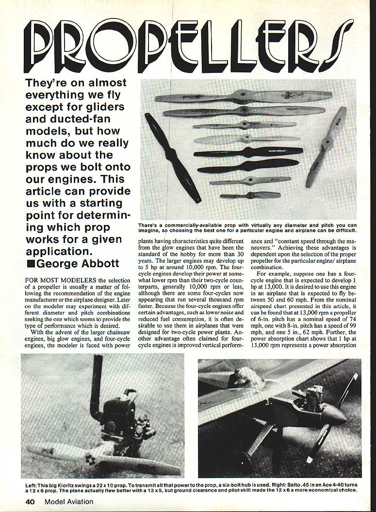
They're on almost everything we fly except for gliders and ducted-fan models. How much do we really know about the props we bolt onto our engines? This article provides a starting point for determining which prop works for a given application.
For most modelers the selection of a propeller is usually a matter of following the recommendation of the engine manufacturer or the airplane designer. Later the modeler may experiment with different diameter and pitch combinations seeking the one that gives the desired performance.
With the advent of larger chainsaw engines, big glow engines, and four-cycle engines, modelers face power plants with characteristics quite different from the glow engines that have been the hobby standard for more than 30 years. Larger engines may develop up to 5 hp at around 10,000 rpm. Four-cycle engines generally develop power at somewhat lower rpm than two-cycles (often 10,000 rpm or less), although some four-cycles now run several thousand rpm faster.
Four-cycle engines offer advantages such as lower noise and reduced fuel consumption, so it is often desirable to use them in airplanes designed for two-cycle power plants. Another advantage often claimed is improved vertical performance and "constant speed through the maneuvers." Achieving these advantages depends on selecting the proper propeller for the particular engine/airplane combination.
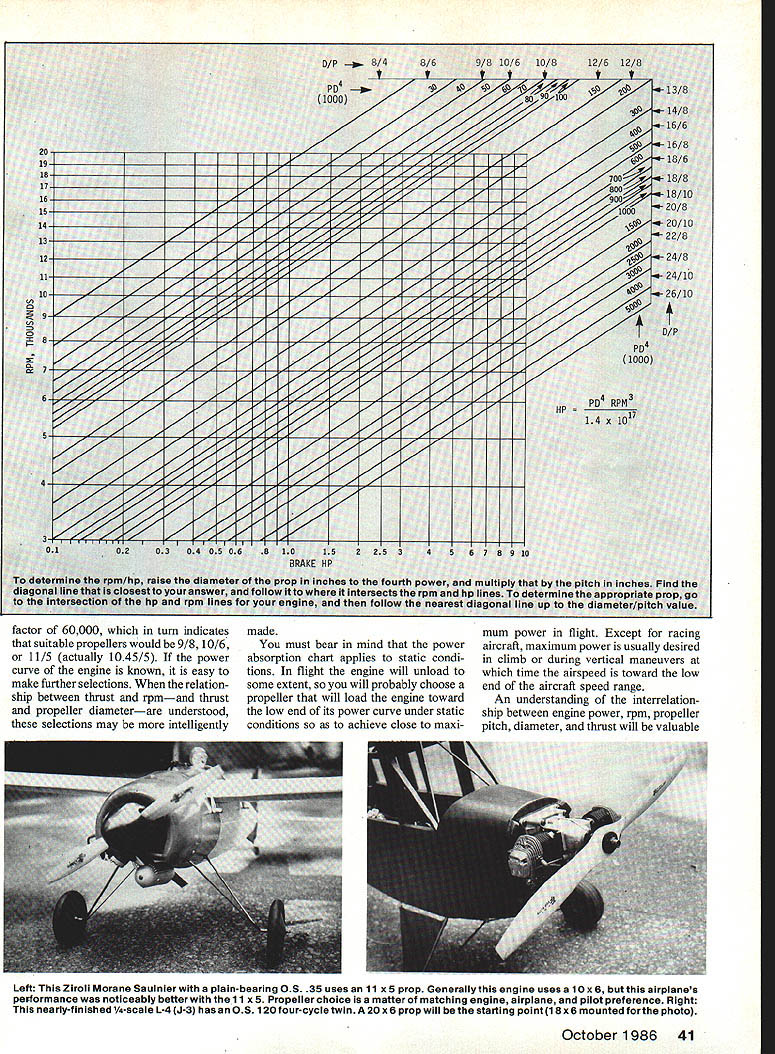
For example, suppose one has a four-cycle engine expected to develop 1 hp at 13,000 rpm, and it is desired to use this engine in an airplane expected to fly between 50 and 60 mph. From the nominal airspeed chart described below, at 13,000 rpm a propeller of 6-in. pitch has a nominal speed of 74 mph, an 8-in. pitch has 99 mph, and a 5-in. pitch about 62 mph. The power absorption chart shows that 1 hp at 13,000 rpm corresponds to a PD^4 factor of about 60,000, which in turn indicates suitable propellers would be 9/8, 10/6, or 11/5 (actually about 10.45/5). If the engine power curve is known, further selections are easy. When the relationship between thrust and rpm—and thrust and propeller diameter—are understood, these selections can be made more intelligently.
You must bear in mind that the power absorption chart applies to static conditions. In flight the engine will unload to some extent, so you will probably choose a propeller that will load the engine toward the low end of its power curve under static conditions to achieve close to maximum power in flight. Except for racing aircraft, maximum power is usually desired in climb or during vertical maneuvers when the airspeed is toward the low end of the aircraft speed range.
An understanding of the interrelationship between engine power, rpm, propeller pitch, diameter, and thrust is valuable. It is particularly useful in selecting a propeller for a particular engine or airplane or in estimating the effectiveness of various fuels or engine modifications.
Terminology
- D = Diameter: the measurement in inches of the prop from tip to tip.
- P = Pitch: the distance in inches that the prop would move forward in one revolution if there were no slippage.
- J = Advance ratio: a measure of the velocity V (airspeed) of the airplane divided by the rotational speed of the propeller and its diameter. J = V ÷ (rpm × D) when consistent units are used. J defines the angle of attack of the propeller airfoil at any airspeed or rpm.
- rpm = Revolutions per minute, the speed of rotation of the propeller.
- hp = Horsepower produced by the engine or absorbed by the propeller. One hp = 33,000 ft-lb/min.
- p = Density of the air (varies with pressure, temperature, humidity), in slugs/ft^3. At standard sea level (29.92 in. Hg, 59°F), p = 0.00237.
This article aims to provide an understanding of propeller operation, not an exhaustive course in aerodynamics. Most readers will buy commercial propellers rather than design them. The definitions above are sufficient for the qualitative discussion that follows.
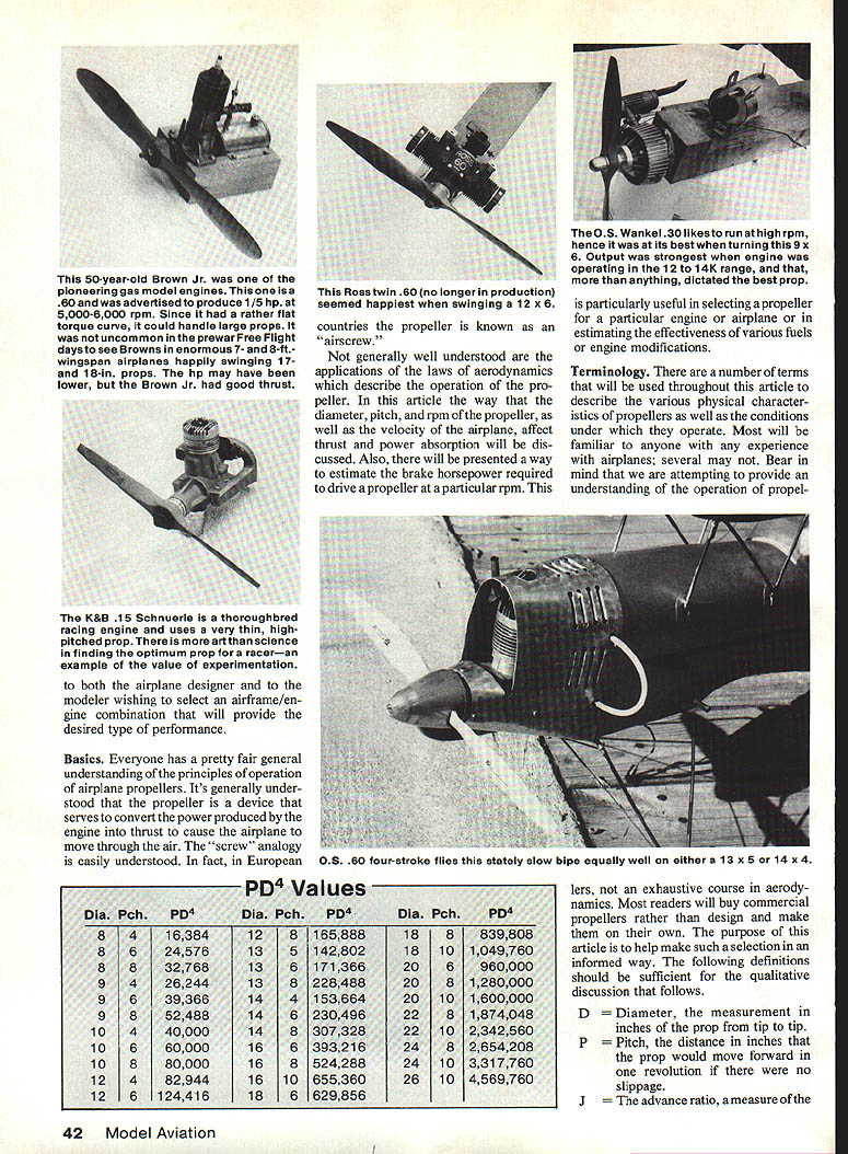
PD^4 Values
To use the prop-power method described later, compute PD^4 (P × D^4). The following are PD^4 values for many common two-blade props (D × P = PD^4):
- 8 × 4 = 16,384
- 8 × 6 = 24,576
- 8 × 8 = 32,768
- 9 × 4 = 26,244
- 9 × 6 = 39,366
- 9 × 8 = 52,488
- 10 × 4 = 40,000
- 10 × 6 = 60,000
- 10 × 8 = 80,000
- 12 × 4 = 82,944
- 12 × 6 = 124,416
- 12 × 8 = 165,888
- 13 × 5 = 142,805
- 13 × 6 = 171,366
- 13 × 8 = 228,488
- 14 × 4 = 153,664
- 14 × 5 = 192,080
- 14 × 6 = 230,496
- 16 × 6 = 393,216
- 16 × 8 = 524,288
- 18 × 6 = 629,856
- 18 × 8 = 839,808
- 20 × 6 = 960,000
- 20 × 8 = 1,280,000
- 20 × 10 = 1,600,000
- 22 × 6 = 1,405,536
- 22 × 8 = 1,874,048
- 22 × 10 = 2,342,560
- 24 × 8 = 2,654,208
- 24 × 10 = 3,317,760
- 26 × 10 = 4,569,760
Note: These values assume typical two-bladed propellers with aspect ratios between about 6:1 and 9:1, common in RC and CL models.
Thrust
Thrust is the force exerted by the rotating propeller in the direction of travel. It converts engine torque into linear force to propel the airplane. The formula for thrust is:
T = p × rpm^2 × D^4 × Ct
- Ct is the thrust coefficient, which depends on the propeller shape, advance ratio J, and Reynolds number. Ct varies with airspeed and propeller geometry, so meaningful absolute Ct values are difficult to obtain for models.
- Important consequence: thrust varies as the fourth power of diameter and the square of rpm. This is because blade lift varies with the square of local velocity, blade local velocity varies with radius, and disk area varies with D^2.
Thus, selecting the largest propeller consistent with desired pitch, rpm, and available power often increases thrust because a larger disk influences a greater volume of air.
Power absorption
Reciprocating model engines exhibit a power curve that increases with rpm to a peak and then falls off. Power = torque × rpm; peak torque typically occurs at a lower rpm than peak power. As rpm increases, torque often falls because breathing (fuel-air intake per stroke) declines.
It is advisable to select a propeller that permits the engine to operate near the rpm for maximum power. Airspeed plays an important part in this decision, which is why adjustable-pitch props were developed for full-size aircraft and have been used on models.
The formula for propeller power (power required to drive a propeller) is:
hp = P × D^4 × rpm^3 × Cp
- Cp is the power coefficient, a function of propeller shape, advance ratio, and Reynolds number. Pitch is included in Cp because it affects propeller shape.
- Key point: propeller power varies as the cube of rpm. Doubling rpm requires eight times the power.
Although Ct values are hard to get for thrust, useful numbers for Cp can be found from historical data and measurements. Because model props operate at Reynolds numbers similar to full-size props (smaller size but much higher speeds), empirical data from the literature can be applied.
The propeller power chart
From research and collected data, the following empirical expression (accurate to roughly ±20%) is useful for static conditions:
hp = (P × D^4 × rpm^3) / (1.4 × 10^11)
- P, D in inches; rpm in rev/min.
- This gives a practical way to estimate the horsepower required to drive a propeller at a given static rpm (advance ratio J = 0).
To use this method, compute PD^4 (P × D^4), which for common props ranges from about 20,000 to 5,000,000. Then:
- If you know a prop (P and D) and rpm, calculate PD^4 and use the formula to estimate hp.
- If you know engine hp and rpm and wish to select a prop, find the intersection of hp and rpm, follow to the required PD^4, then choose pitch and diameter combinations that yield that PD^4.
- To find diameter from a PD^4 value, take the fourth root (use a scientific calculator, e.g., enter PD^4^(0.25)).
A graphical chart can make this process easier: locate PD^4 on the chart and read off hp at any rpm or vice versa. If your PD^4 does not exactly match chart values, interpolate between lines or use the formula for greater accuracy.
This method works for typical two-blade props of the aspect ratios noted earlier. It has been checked against full-size and light aircraft data and generally yields results within about ±15% for model purposes.
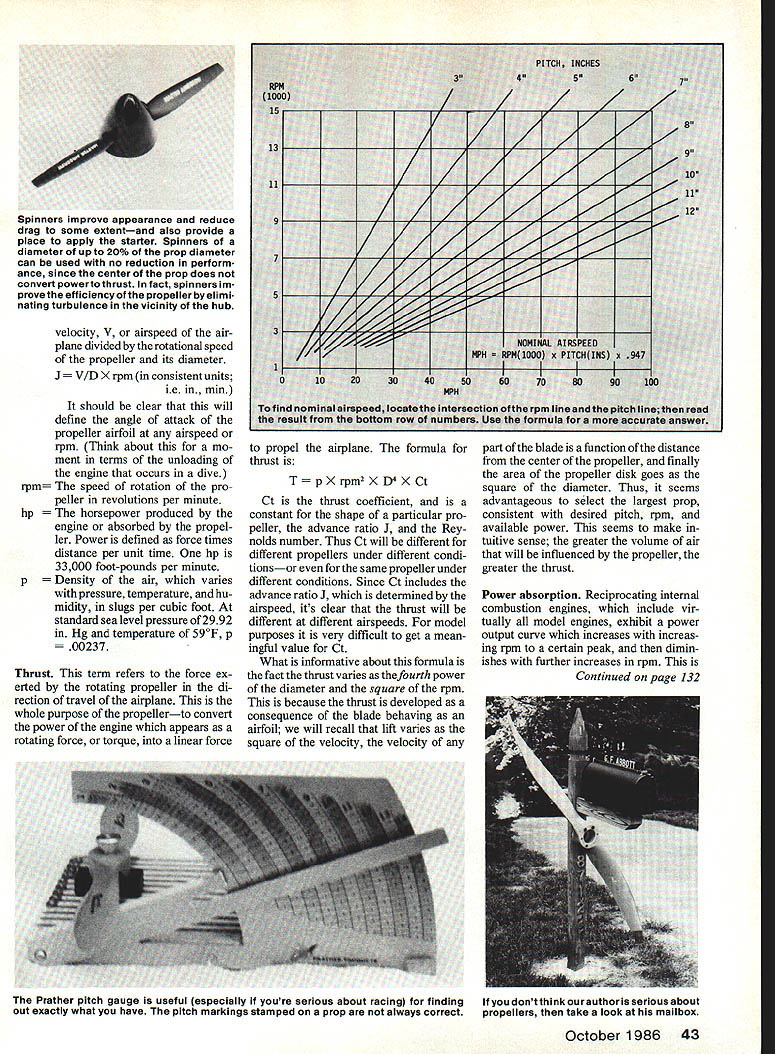
Nominal airspeed
It is useful to estimate the airspeed range expected with a particular prop at a given rpm. The simple formula relating pitch, airspeed, and rpm (assuming no slippage) is:
mph = (rpm in thousands) × pitch (in.) × 0.947
This "nominal airspeed" is the speed that would result if the propeller operated with zero slip. In practice slip occurs, so actual speeds are lower, but the nominal speed gives valuable insight for prop selection.
Example: If an airplane is planned to fly at 75 mph and the engine runs at 10,000 rpm, then:
- rpm (thousands) = 10
- Required pitch ≈ 75 ÷ (10 × 0.947) ≈ 7.9 in
So an 8-in. pitch prop would be appropriate to reach roughly 75 mph (neglecting slip).
Bear in mind that under some conditions speeds slightly in excess of the nominal airspeed can be achieved because the blade airfoil can produce lift at a slightly negative angle of attack.
Conclusion
We discussed two formulas describing important aspects of propeller behavior: thrust and power absorption.
- From the thrust formula, the importance of diameter (disk area) is apparent: thrust varies strongly with D^4.
- From the power discussion, propeller power varies as rpm^3, so modest changes in rpm require large changes in power.
A practical empirical formula and accompanying PD^4 values allow estimation of the static horsepower required to drive common model propellers at given rpm. The nominal airspeed formula helps relate pitch and rpm to expected speed (neglecting slip). These tools are valuable when selecting a propeller for a particular engine/airplane combination.
Transcribed from original scans by AI. Minor OCR errors may remain.

