
Protobype
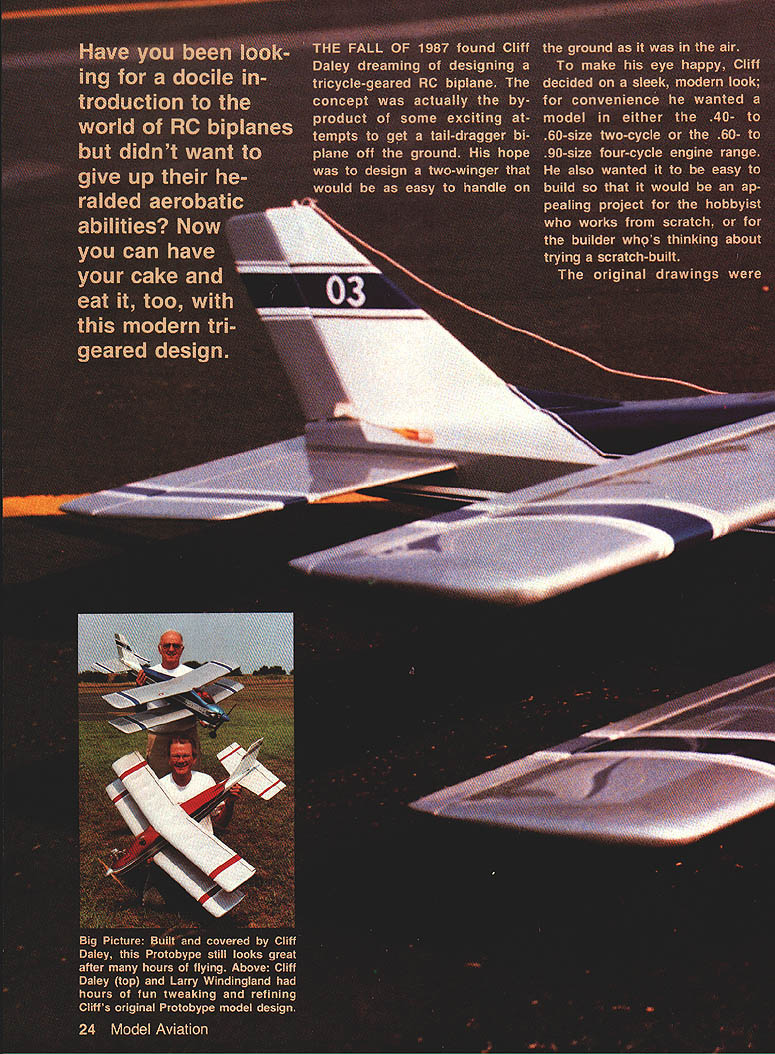
Have you been looking for a docile introduction to the world of RC biplanes but didn't want to give up their heralded aerobatic abilities? Now you can have your cake and eat it, too, with this modern tri-geared design.
The fall of 1987 found Cliff Daley dreaming of designing a tricycle-geared RC biplane. The concept was actually the byproduct of some exciting attempts to get a tail-dragger biplane off the ground. His hope was to design a two-winger that would be as easy to handle on the ground as it was in the air.
To make his eye happy, Cliff decided on a sleek, modern look; for convenience he wanted a model in either the .40–.60-size two-cycle or the .60–.90-size four-cycle engine range. He also wanted it to be easy to build so that it would be an appealing project for the hobbyist who works from scratch, or for the builder thinking about trying a scratch-built.
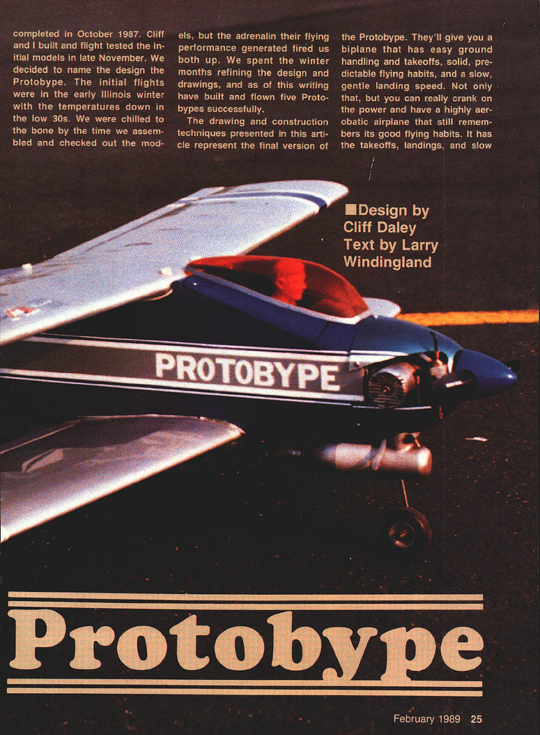
The original drawings were completed in October 1987. Cliff and I built and flight-tested the initial models in late November. We decided to name the design the Protobype. The initial flights were in the early Illinois winter with temperatures in the low 30s. We were chilled to the bone by the time we assembled and checked out the models, but the adrenaline their flying performance generated fired us both up. We spent the winter months refining the design and drawings, and as of this writing have built and flown five Protobypes successfully.
The drawing and construction techniques presented here represent the final version of the Protobype. They'll give you a biplane that has easy ground handling and takeoffs, solid, predictable flying habits, and a slow, gentle landing speed. Not only that, but you can really crank on the power and have a highly aerobatic airplane that still remembers its good flying habits. It has the takeoffs, landings, and slow stall speed of a primary trainer, yet it can fly like an aerobatic trainer.
The Protobype requires no interplane or cabane struts to support the wings, which are even interchangeable. An unexpected bonus in this model's way of flying is that the rudder produces nearly pure yaw with almost no noticeable roll coupling. This characteristic makes the plane great for knife-edge flight, axial rolls, and slip practice.
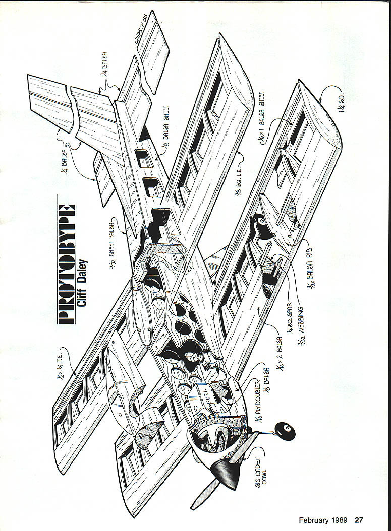
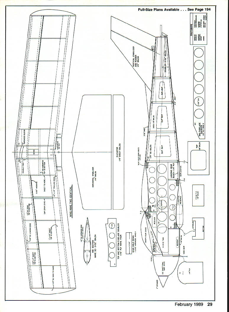
Wing panels (make two identical upper and two identical lower)
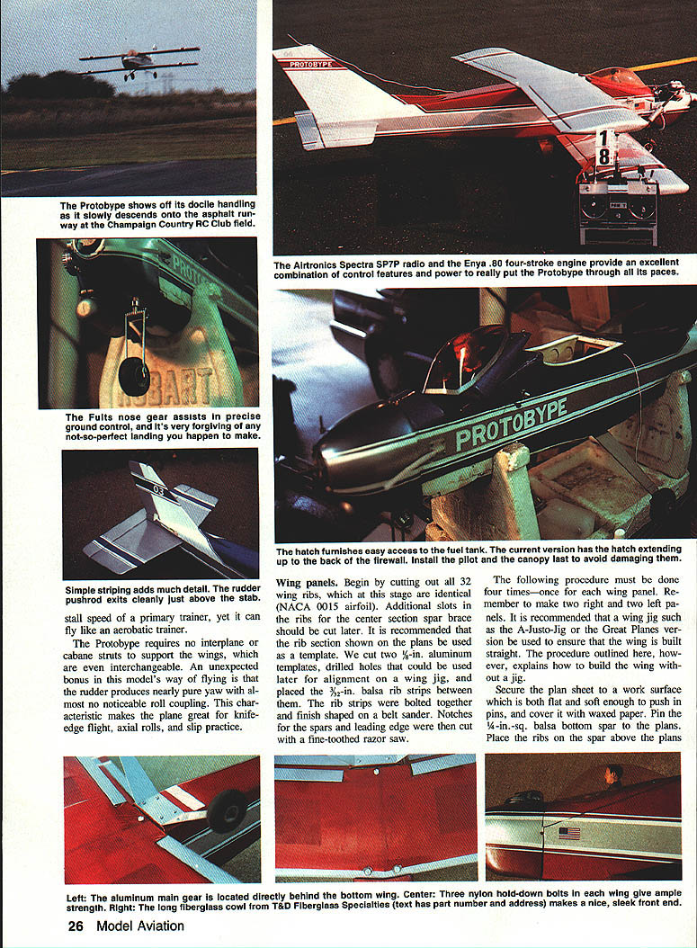
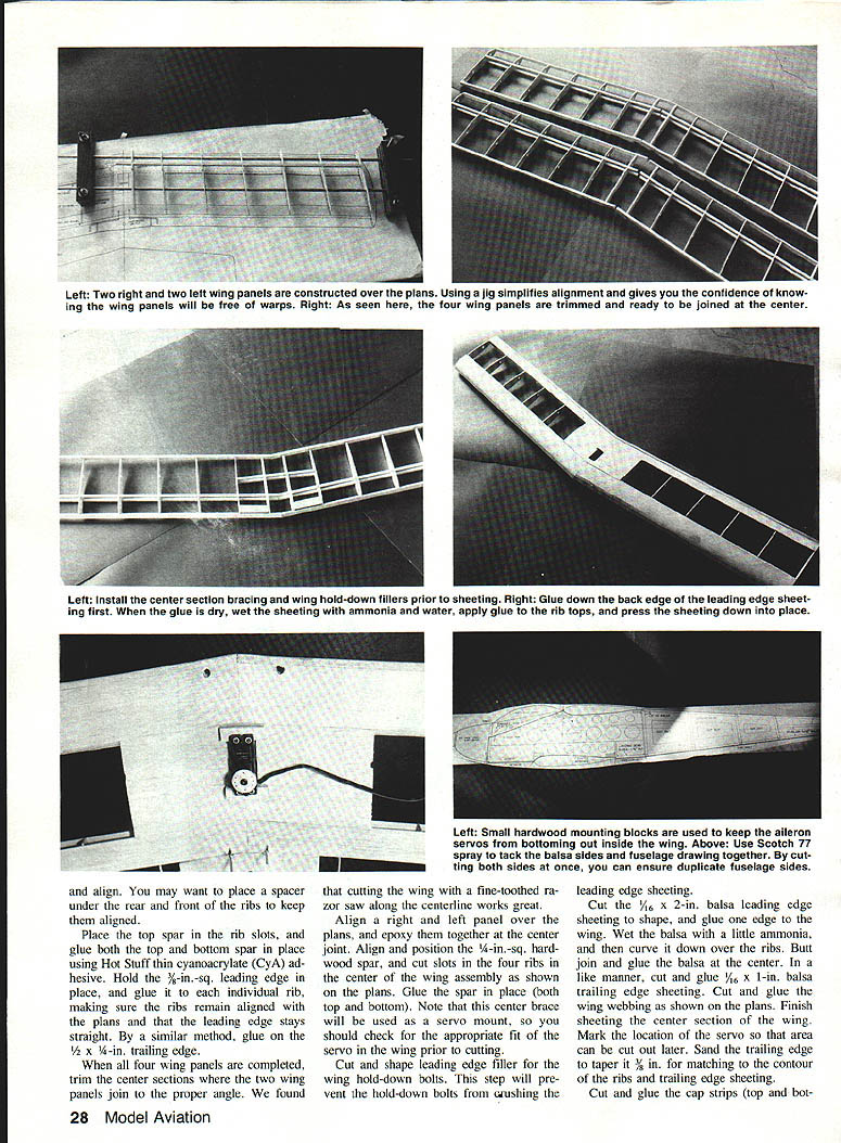
Begin by cutting out all 32 wing ribs; at this stage they are identical (NACA 0015 airfoil). Additional slots in the ribs for the center-section spar brace should be cut later. It is recommended that the rib section shown on the plans be used as a template. We cut two 1/8-in. aluminum templates, drilled holes for alignment on a wing jig, placed the 3/8-in. balsa rib strips between the templates, bolted them together, and finish-shaped on a belt sander. Notches for the spars and leading edge were then cut with a fine-toothed razor saw.
The following procedure must be done four times—once for each wing panel. Remember to make two right and two left panels. It is recommended that a wing jig such as the A-Justo-Jig or the Great Planes version be used to ensure that the wing is built straight. The procedure outlined here, however, explains how to build the wing without a jig.
- Secure the plan sheet to a flat work surface that is soft enough to push in pins, and cover it with waxed paper. Pin the 1/4-in.-sq. balsa bottom spar to the plans. Place the ribs on the spar above the plans.
- Glue down the back-edge leading-edge sheeting first. When gluing sheeting, wet the sheet with ammonia and water to help it conform. Apply glue to the rib tops and press the sheeting down in place. You may want to place a spacer under the rear of the front ribs to keep them aligned.
- Place the top spar in the rib slots and glue both top and bottom spars in place using Hot Stuff thin cyanoacrylate (CA) adhesive. Hold a 1/4-in.-sq. leading edge in place and glue to each rib, making sure the ribs remain aligned and that the plans' leading edge stays straight. In a similar manner, glue the trailing edge.
- Cut 1/16-in. x 2-in. balsa leading-edge sheeting, shape it, and glue it to the edge of the wing. Wet the balsa with a little ammonia to help it curve down over the ribs. Butt-join and glue the balsa at the center in the same manner.
- Cut and glue 1/16-in. x 1-in. balsa trailing-edge sheeting. Cut and glue the wing webbing as shown on the plans. Finish sheeting the center section of the wing.
- Mark the location of the servo area (this can be cut out later). Sand the trailing edge taper to match the contour of the ribs and trailing-edge sheeting. Cut and glue cap strips on both top and bottom.
- Sheet the wing tips with 1/16-in. balsa and finish shaping.
After the four wing panels are completed, trim the center sections of the two panels to be joined and form the proper dihedral/angle. A good way to find the proper angle is to cut the wing along the centerline with a fine-toothed razor saw. Align the right and left panels over the plans and epoxy them together at the center joint.
Align a 1/4-in.-sq. hardwood spar in position and cut slots in the four center ribs; glue the spar in place at both top and bottom. Note that the center brace will be used as the servo mount—check for appropriate servo fit in the wing prior to cutting.
Cut and glue the leading-edge filler to prevent the wing hold-down bolts from crushing the leading-edge sheeting. Cut and glue additional wing webbing and finish the center-section sheeting per the plans.
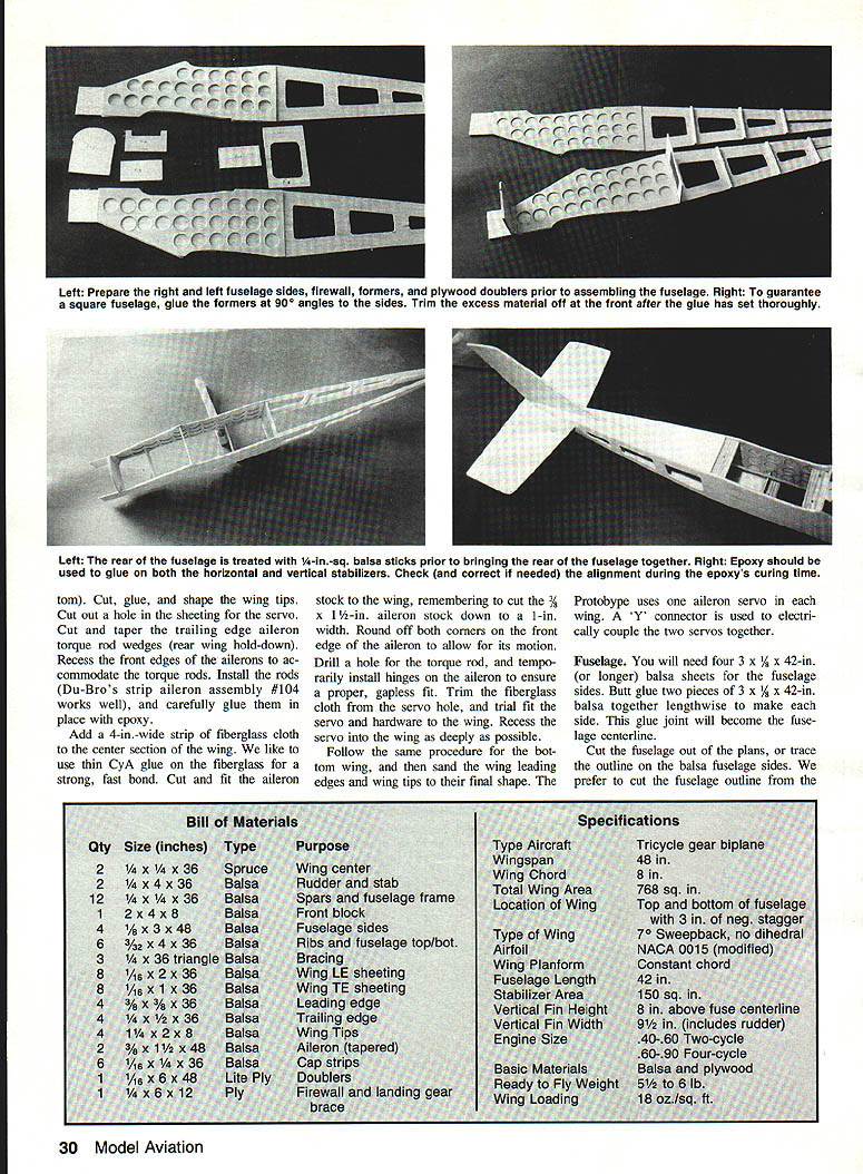
Add a 4-in.-wide strip of fiberglass cloth to the center section of the wing. We like to use thin CA on the fiberglass for a strong, fast bond. Cut and fit the aileron stock to the wing, remembering to cut the 3-1/2-in. aileron stock down to a 1/8-in. width. Round off both corners on the front edge of the aileron to allow for its motion.
Drill a hole for the torque rod, and temporarily install hinges on the aileron to ensure a proper, gapless fit. Trim the fiberglass cloth from the servo hole, and trial-fit the servo and hardware to the wing. Set the servo into the wing as deeply as possible.
Follow the same procedure for the bottom wing, and then sand the wing leading edges and wing tips to their final shape. The Protobype uses one aileron servo in each wing. A "Y" connector is used to electrically couple the two servos together.
Cut and glue small hardwood mounting blocks to keep the aileron servos from bottoming out inside the wing. Cut and glue leading-edge filler for the wing hold-down bolts as needed.
Horizontal stabilizer (1/8-in. sheet balsa)
Cut out the stabilizer parts per the plans. Trial-fit the horizontal stabilizer in the slot at the rear of the fuselage. Align the stab so it is centered, 90° to the fuselage sides, and with tips equidistant from the front of the fuselage. When all three adjustments are correct, glue the stabilizer in place with epoxy. Sheet and finish as shown on the plans.
Elevator (1/8-in. sheet balsa)
Cut out the elevator per the plans. Trial-fit and temporarily hinge the elevator to ensure proper movement and alignment before final installation.
Landing gear box / Nose gear
Locate the aluminum main gear directly behind the bottom wing. The main gear should be about 3 3/4 to 4 in. wide at the fuselage and about 12 in. wide at the wheels. Two-inch lightweight wheels are used for hard-surface runways; for grass runways, at least 2 1/2-in. wheels are recommended.
A Fults nose gear assists precise ground control. The standard nose wheel gear can be installed in the small nose gear block mounted underneath the engine. Three nylon wing hold-down bolts give ample strength.
Cut and glue the landing gear block and secure it with 1/4-in. triangle stock. Install 1/4-in. triangle stock around formers for added strength as shown on the plans.
Fuselage
You will need four 3 x 1/2 x 42-in. (or longer) balsa sheers for the fuselage sides. Butt-glue two pieces of 3 x 1/2 x 42-in. balsa together lengthwise to make each side. This glue joint will become the fuselage centerline.
Use Scotch 77 spray to tack the balsa sides to the fuselage plan; cutting both sides at once will help ensure duplicate fuselage sides. Cut the fuselage outline from the plans or trace it onto the balsa fuselage sides. Sand the edges to final shape, keeping the sides identical; after separating the sides, mark them left and right.
Cut the fuselage doublers from 3/32-in. plywood. You can use three separate pieces for each side as shown on the plans or a one-piece doubler cut from a 6-in.-wide piece of plywood. Lightening holes can be cut using a hole saw attached to a drill. Glue the plywood doublers to the inside of the fuselage sides as shown on the plans. Cut and glue horizontal stabilizer doublers at the rear of the fuselage.
Cut out fuselage formers F-1 to F-5. Trial fit these formers to the fuselage and glue them in place using the plans as a guide. Use epoxy on the firewall. Align the sides and formers carefully to ensure the formers are at 90° to the fuselage sides. Check alignment at both the front and rear of the fuselage.
Cut and glue 1/4-in.-sq. balsa sticks to the inside of the fuselage sides from behind former F-5 to the rear of the aircraft. Fit the lengthwise pieces first, then fill in the vertical sticks. Bring the rear fuselage sides together and taper the 1/4-in.-sq. sticks so they just disappear at the rearmost part of the fuselage. When aligned, glue them together with CA. Install 1/4-in.-sq. horizontal balsa crosspieces at the locations of the vertical sticks previously glued.
Sheet the top and bottom of the fuselage with 3/32-in. balsa. Cut and trial-fit the vertical stabilizer, ensuring it is 90° to the horizontal stab and perfectly in line with the fuselage centerline. Glue it in place with epoxy.
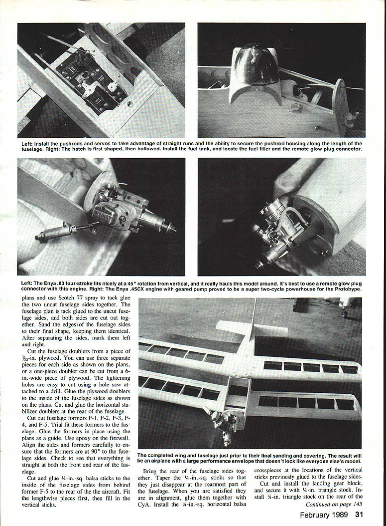
Working from the bottom of the fuselage, define the pushrod exits and install guides for the elevator and rudder. Fasten the pushrod guides at several locations along their length.
Cut, shape, and trial-fit the hatch on the top of the fuselage. Make this structure removable for access to the fuel tank, battery, and receiver; one method is shown on the plans. The hatch should be rounded from F-1 to the leading edge of the top wing. The cowl fits over the firewall, so sand the hatch lightly to avoid making it undersized. Install the pilot canopy last to avoid damaging it.
Final assembly
- Trial-fit the engine to the mount and hold the assembly up to the firewall to determine desired location. Ensure sufficient clearance for the muffler. The prototype used an Enya .80 four-cycle or an Enya .45 CX with geared pump, mounted at a 45° sideways position (engine rotated 45° to the right when viewed from the rear). The model requires no right or downthrust. The centerline location of the engine is governed by the cowling used.
- For four-cycle installations, a fiberglass cowl (SK-1FC) from T & D Fiberglass Specialties is recommended. Their address: T & D Fiberglass Specialties, 30925 Block, Garden City, MI 48135. Phone: (313) 421-6538.
- Mark the firewall for blind-nut placement, drill the holes and install blind nuts. Temporarily attach the engine and work out routing of throttle and nose wheel steering pushrods.
- Trial-fit the fuel tank and decide fuel tubing routing. Drill firewall holes for pushrods and fuel tubing. If using a remote filler (Du-Bro Kwik-Fill Fuel Valve, Robart SuperFiller II, or Ultra Filler) or a remote glow plug (highly recommended for four-cycle installations), determine location and trial fit at this time.
- Hold the cowl to the engine, determine where it must be recessed, cut and fit the cowl for final fit, and secure it with small screws to the firewall sides. Sand the hatch to final shape.
- Install the hardwood wing hold-down blocks as shown on the plans. Trial-fit the top wing to the fuselage and check incidence. The top wing should be at zero degrees incidence using the horizontal stabilizer as a reference. If you don't have an incidence meter, measure leading and trailing edges to be equidistant from the fuselage centerline. Sand the fuselage wing cradle as needed to achieve 0°.
- Align the top wing centered left-to-right so wing tips are equal distances from horizontal stabilizer tips. When properly aligned, drill 3/16-in. pilot holes through the wing and hold-down blocks at locations shown on the plans. Remove the wing and drill holes for 1/4-20 nylon bolts and install blind nuts in the hold-down blocks.
- For the bottom wing, place it at one degree positive incidence (leading edge approximately 1/8 in. higher than trailing edge). Follow the same drilling and blind-nut installation procedure.
- Trial-fit the aluminum landing gear to the fuselage bottom just behind the trailing edge of the wing.
- Check the balance point and determine best locations for servos, receiver, battery, switch, and charging jack. Position components to make the model balance at the point shown on the plans. Install servos, ensuring sufficient clearance for the wing servos.
- Remove hardware and engine. Brush epoxy or fuel-proof dope on the inside of the tank compartment and on the firewall. Sand and finish wire the wings and fuselage to final shape, and glue in the canopy.
- After final sanding, the Protobype is ready to cover.
As a design alternative, you could raise the top wing 2 in., add an extra doubler and balsa to the fuselage sides, and convert the design to a cabin model.
Covering
You can use any commercial heat-shrink material. We used MonoKote and Black Baron Metalflake on various editions of the model, and both worked well. The trim scheme is up to you.
When the model is completed, reinstall all hardware, radio gear, and the engine. Glue in all hinges, install wing seating tape, and set the throws of the control surfaces:
- Aileron total throw: 3/8 in.
- Rudder throw: 1 1/2 in.
- Elevator throw: 3/16 in.
Make a final check of the balance point.
Radio
The prototype used an Airtronics Spectra SP7P radio. This narrow-band FM/PCM radio includes servo reverse, adjustable throw volume for aileron, elevator, and rudder, adjustable low throttle, coupling/mixing, a snap roll button, linear and exponential control action, and dual rates. Other features include a plug-in transmitter battery and plug-in RF module, an audible low-voltage alarm, and a fail-safe mode that can be preset or default to the most recent command. The radio system also has a 1991-rated receiver—ours performed flawlessly.
Engine
The Enya engines used on the Protobype are distributed in the United States by Altech Marketing. The .45-size two-cycle is a Schnuerle-ported, chrome-liner engine with a geared fuel pump, rated at 1.3 horsepower and weighing 12.3 oz. without the muffler—an excellent two-cycle choice. The .80-size four-cycle claims 1.1 horsepower and weighs 20.7 oz., a great power-to-weight ratio for a four-cycle. Both engines perform extremely well in the Protobype models. Your local hobby shop should be able to obtain these engines.
Flight
The Protobype is recommended for the flier with early intermediate-level skills. Handling characteristics, determined by your adjustments of the control-surface throws, can be as gentle as you like. This biplane can be docile as a trainer or as aerobatic as you are capable of handling. We're sure the Protobype will provide hours of pleasure in both building and flying. Good flying!
Bill of Materials
- Qty / Size (in.) / Type / Purpose
- 2 / 1/4 x 1/4 x 36 / Spruce / Wing center
- 2 / 1/4 x 4 x 36 / Balsa / Rudder and stab
- 12 / 1/4 x 1/4 x 36 / Balsa / Spars and fuselage frame
- 2 / 1/2 x 4 x 8 / Balsa / Front block
- 4 / 1/8 x 3 x 48 / Balsa / Fuselage sides
- 6 / 3/32 x 4 x 36 / Balsa / Ribs and fuselage top/bottom
- 8 / 1/16 x 3 x 36 / Balsa / Bracing
- 8 / 1/16 x 2 x 36 / Balsa / Wing LE sheeting
- 8 / 1/16 x 1 x 36 / Balsa / Wing TE sheeting
- 4 / 3/32 x 3 x 36 / Balsa / Leading edge
- 4 / 1/16 x 3 x 36 / Balsa / Trailing edge
- 4 / 1/16 x 2 x 8 / Balsa / Wing tips
- 2 / 1/16 x 1/4 x 48 / Balsa / Aileron (tapered)
- 1 / 1/16 x 1/4 x 36 / Balsa / Cap strips
- 1 / 1/8 x 1/4 x 36 / Balsa / Doublers
- 1 / 1/16 x 6 x 48 / Lite Ply / Firewall and landing gear brace
Specifications
- Type Aircraft: Tricycle gear biplane
- Wingspan: 48 in.
- Wing Chord: 8 in.
- Total Wing Area: 768 sq. in.
- Location of Wing: Top and bottom of fuselage with 3 in. of negative stagger
- Type of Wing: 7° sweepback, no dihedral
- Airfoil: NACA 0015 (modified)
- Wing Planform: Constant chord
- Fuselage Length: 42 in.
- Stabilizer Area: 150 sq. in.
- Vertical Fin Height: 8 in. above fuselage centerline
- Vertical Fin Width: 9-1/2 in. (includes rudder)
- Engine Size: .40–.60 two-cycle; .60–.90 four-cycle
- Basic Materials: Balsa and plywood
- Ready-to-Fly Weight: 5-1/2 to 6 lb.
- Wing Loading: 18 oz./sq. ft.
Transcribed from original scans by AI. Minor OCR errors may remain.

