
Pulsemaster 64
This simple circuit for use with the Commodore C-64 computer can provide a wealth of information about the performance of your servos and transmitter.
Bernard L. Stuecker
PULSES: they're the heartbeat of nearly all modern R/C systems. Pulses tell a servo what position to assume. They are sent out of the transmitter in a serial stream — channel #1 first, channel #2 second, and so on. After the last channel is sent, the transmitter issues a "sync" pulse and then starts over.
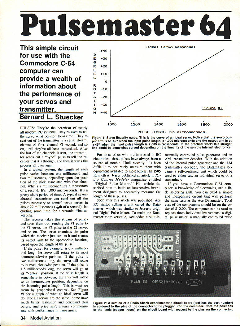
In a typical system, each pulse length varies between about 1.0 millisecond and 2.0 milliseconds, depending on stick position (1 ms = 1,000 microseconds). A typical seven-channel transmitter can send all pulses in roughly 22 milliseconds (1/45th of a second), including housekeeping time. The receiver sorts the stream and sends the correct pulse to each servo; the servo rotates its arm according to pulse length: ~1.0 ms = full counterclockwise, ~2.0 ms = full clockwise, ~1.5 ms = center. Intermediate pulse lengths produce intermediate positions — this is proportional control.
Until recently, accurately measuring pulse length required specialized gear. In 1985 Kenneth A. Jesser described an inexpensive Digital Pulse Meter. Ace RC later sold a similar product, the Datamaster, which added a manual pulse generator and an AM transmitter decoder. If you have a Commodore C-64, basic electronics skill, and a little soldering, you can build a simple, low-cost circuit (components around $10) and use the C-64 to replace a digital pulse meter, a manual pulse generator, and an AM transmitter decoder.
The system uses the 6526 Complex Interface Adapter (CIA) inside the Commodore C-64 to generate outgoing pulses and to time incoming pulses. The CIA includes hardware timers/counters that measure intervals from microseconds to about 70 seconds with 1-microsecond resolution. These timers are crystal-controlled for accuracy and stability. Access to the CIA is provided via the C-64 User Port, whose output lines can generate very accurately timed pulses sufficient to drive standard RC servos directly.
With this setup you can:
- Operate a servo to check resolution, deadband, centering, end points, and linearity.
- Slowly creep a servo through its range to check for defective spots on the potentiometer or motor commutator (manifest as jitter).
- Rapidly or automatically cycle a servo from end to end.
- Measure transmitter pulse lengths accurately to the nearest microsecond.
About the Author
Bernie Stuecker has been involved in R/C since 1979 as a member of the Northern Virginia Radio Control Club (NVRCC). He is a past president of NVRCC and currently edits the club newsletter, Feedback. Bernie is an electronics engineer by profession, has been an amateur radio operator for nearly 25 years (call sign K4XY), and enjoys photography and model aviation.
Why measure incoming pulse length?
- Standardizing equipment
- With modern transmitters offering mixing, centering, end-point adjustments, exponential rates, etc., it's easy to lose a known baseline.
- Measuring center and end points of each channel while readjusting ensures all transmitter settings are restored to a uniform reference.
- Useful for matching transmitters in buddy-box systems so instructor and student have equal control throw.
- Re-establishing settings between airplanes
- If one transmitter is used on multiple planes with different trim/throw requirements, accurate measurements let you record and later restore optimum settings for each plane.
- Checking stability over temperature
- Test transmitter stability by powering it cold (e.g., from a freezer), then measuring pulse lengths as it warms to room temperature. Some receivers/servos may fail or shift at low temperatures.
- Checking stability over time (battery discharge)
- Measure pulse lengths at intervals as the transmitter battery discharges to detect trim changes caused by power sag.
Other benefits: If all transmitters are set to a common neutral pulse length, you can interchange servos/receivers/transmitters with less concern about mismatched pulse standards (assuming connectors and positive-pulse systems match).
About the circuit
- The servo lead can be connected directly to the C-64 User Port; the CIA chip is a 5-volt CMOS device and generates pulses compatible with standard RC servos — no interface required if you only want to drive servos.
- To measure transmitter pulses from a receiver reliably with all receivers tested, a small buffer circuit is recommended for the incoming signal. The buffer used consists of two resistors and a PNP transistor (e.g., 2N3638) to provide gain and isolation between the receiver and the computer input. With the buffer, the computer has worked with all positive-pulse receivers tested.
- The timers inside the CIA provide microsecond resolution, and the User Port outputs produce stable, accurately timed pulses for servo testing and generation.
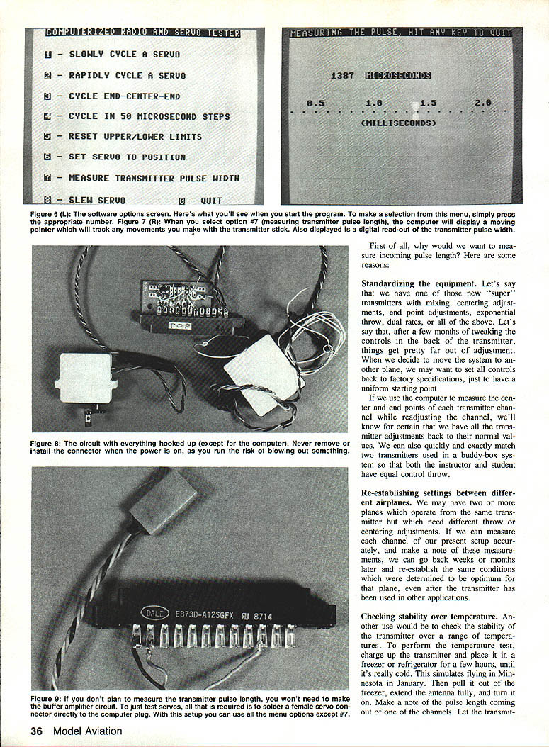
Connector and User Port notes
- The PC card edge connector that mates with the C-64 User Port typically has two key slots that align with two keys on the computer's User Port circuit board. Make sure your connector has keys positioned correctly (slots between the contacts). If keys aren't supplied with the connector, you can fashion plastic keys (for example, from R/C hinge material) and glue them in place to prevent incorrect insertion.
- The edge connector has a dual row of contacts (12 top, 12 bottom). Do not use a connector where top and bottom pins are internally tied together — that can damage the computer.
- Be very careful when inserting the connector; it will fit either right side up or upside down. Ensure correct orientation. Never plug the PC card edge connector into the computer while the computer is turned on — you could blow the computer fuse or cause more serious damage.
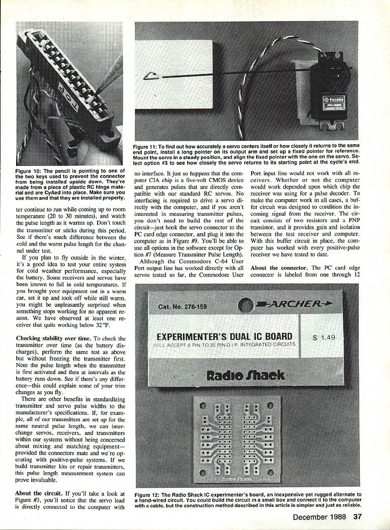
Building the circuit
- The circuit was built on 1/4 of a Radio Shack Experimenters Dual IC Board (catalog #276-159). A quarter section was cut off and soldered to the bottom row of contacts on the PC card edge connector that mates with the C-64 User Port.
- Required components:
- 1 PNP silicon transistor (2N3638, MPS2907, or similar general-purpose small-signal PNP)
- 1 4.7K ohm, 1/4W resistor
- 1 22K ohm, 1/4W resistor
- 1 aileron extension (or other connector pair compatible with your radio system)
- Solder, wire, and small hand tools
- Solder the circuit board directly to the edge connector pins; align pins to the proper lands. The aileron extension provides a convenient male/female servo connector interface.
Operating the software
Once the software is loaded and running on the C-64, a menu presents the following options:
1) Slowly cycle a servo 2) Rapidly cycle a servo 3) Cycle end-center-end 4) Cycle in 50 microsecond steps (for testing linearity) 5) Reset upper and lower limits (to accommodate various systems) 6) Set servo to a position 7) Measure transmitter pulse length 8) Slew the servo 0) Quit
To select an option, enter the number of the desired option.
What the options do
- Slowly cycle a servo
- Use this to detect erratic servo behavior or jitter. If jitter is observed, the pot or motor may be faulty. Some pots can be cleaned; sealed servos must be replaced or repaired.
- Rapidly cycle a servo
- Drives the servo from one end to the other to "burn in" or exercise the servo. Use 30 seconds to a minute for testing.
- Cycle end-center-end
- Tests resolution and centering. Before using, run Option 5 if your radio system uses nonstandard lower/upper limits. This routine moves the servo end-to-end and pauses at center; attach a long pointer and set a stationary reference to observe centering.
- Cycle in 50 microsecond steps (testing linearity)
- Increments servo position in 50 µs steps and displays a graph. It takes about 2,000 steps to traverse the full range — be patient. Linearity: a truly linear servo moves equal angular increments for equal pulse increments.
- Reset upper and lower limits
- Set the actual pulse lengths corresponding to servo end points. Defaults are 1,000 µs (lower) and 2,000 µs (upper). Some systems (e.g., Futaba AM series) use different limits (e.g., 0.81 ms to 1.81 ms; center 1.310 ms).
- Set servo to a position
- Enter a pulse length (in microseconds) to position the servo. Software-limited to 500–2,500 µs to reduce risk of mechanical damage. Many servos will hit mechanical stops before these extremes; unplug the servo quickly if it jams.
Deadband check:
- Type a pulse near center (1500 µs), then type a slightly different value (e.g., 1505 µs).
- If the servo doesn't move, you're inside the deadband. Increase until you hear the motor "kick." The difference is the deadband in microseconds.
Resolution check:
- Secure the servo, attach a long pointer, center it at 1500 µs, mark the pointer tip, move to another position, then return to 1500 µs. The closer the pointer returns to the mark, the better the resolution.
- Measure transmitter pulse length
- Requires the receiver to be compatible with your transmitter and the computer (buffer recommended). Connect the computer to the desired channel on the receiver after disconnecting all other receiver leads including the battery. The computer supplies receiver power through the User Port and reads incoming pulses for pulse-length measurement.
- When running, the screen displays a horizontal scale (milliseconds) with a moving pointer following stick motion plus a numeric readout to the nearest microsecond.
- Use this to measure stick endpoint travel and neutral repeatability. If the stick does not return to the same neutral reading consistently, the stick may be "sticky."
- Caution: If you select Option 7 without a receiver connected or without a transmitter running, the computer appears to lock up — it is waiting for an incoming pulse. To break out, hold Run/Stop and tap Restore.
- Slew the servo
- Move the servo slowly using the arrow keys while the screen displays the pulse length to the nearest microsecond. Useful for plotting pulse length vs. servo rotation to check linearity.
After testing:
- Turn off the computer and disconnect the unit from the User Port and receiver before reconnecting the receiver battery or reinstalling the receiver in the model. Failure to remove the receiver battery while a receiver is connected to the computer may damage the computer power supply.
Parts List
- 1 ea. Aileron connector to match your radio system (or other compatible servo lead)
- 1 ea. PC card edge connector to match the Commodore 64: GC Electronics part #41-804 or #41-816; Amphenol part #225-12-2-4-1-01; or Cinch part #25-12-30-106 (do not use connectors with top and bottom pins internally connected)
- 1 ea. Experimenter's Dual IC Board: Radio Shack catalog #276-159
- 1 ea. 2N3638, MPS2907, or other PNP small-signal transistor: Radio Shack catalog #276-202
- 1 ea. 4.7K ohm, 1/4-watt resistor: Radio Shack catalog #271-1330
- 1 ea. 22K ohm, 1/4-watt resistor: Radio Shack catalog #271-1339
- Solder, wire, and miscellaneous small hand tools
Cost notes:
- The PC card edge connector at electronics dealers is approximately $3.75. Jameco lists similar parts (part #12/245E) at about $1.49 but has minimum order and handling fees.
Software and availability
- The program listing is lengthy; the software is available on a Commodore diskette from the author for a nominal fee to cover disk, mailer, and postage. It is also available on Compuserve.
- To obtain the diskette: send $4.00 (check or money order) to cover diskette, mailer, and postage to:
Bernard L. Stuecker 2433 Carey Ln. Vienna, VA 22180
- Compuserve: GO MODEM/1 and find the program in Library 11 with the command BRO KEY: SERVO. For Compuserve subscription information, call (800) 848-8199.
- If you have questions or need more information, write to the author (include a stamped, self-addressed envelope).
Final notes and cautions
- If you only want to drive a servo and are not measuring transmitter pulses, you can skip the buffer circuit and simply hook the servo connector to the PC card edge connector and plug into the computer User Port. All software options except Option 7 will be usable.
- Always ensure correct connector orientation and power-down the computer before connecting or disconnecting the PC card edge connector.
- When measuring transmitter pulses, disconnect other receiver leads and the receiver battery as instructed to avoid damage.
- This computerized servo/transmitter checker is inexpensive and can be a useful club project or service tool. For about an hour's work and a small parts cost, you can build a versatile tester that replaces several separate instruments.
Transcribed from original scans by AI. Minor OCR errors may remain.

