
Push-Pull
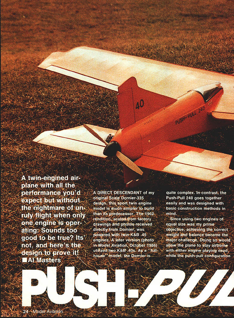
A twin-engined airplane with all the performance you'd expect but without the nightmare of unruly flight when only one engine is operating? Sounds too good to be true? It's not, and here's the design to prove it! — Al Masters
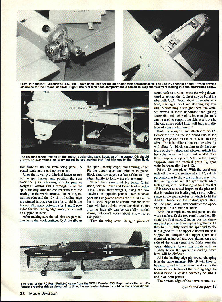
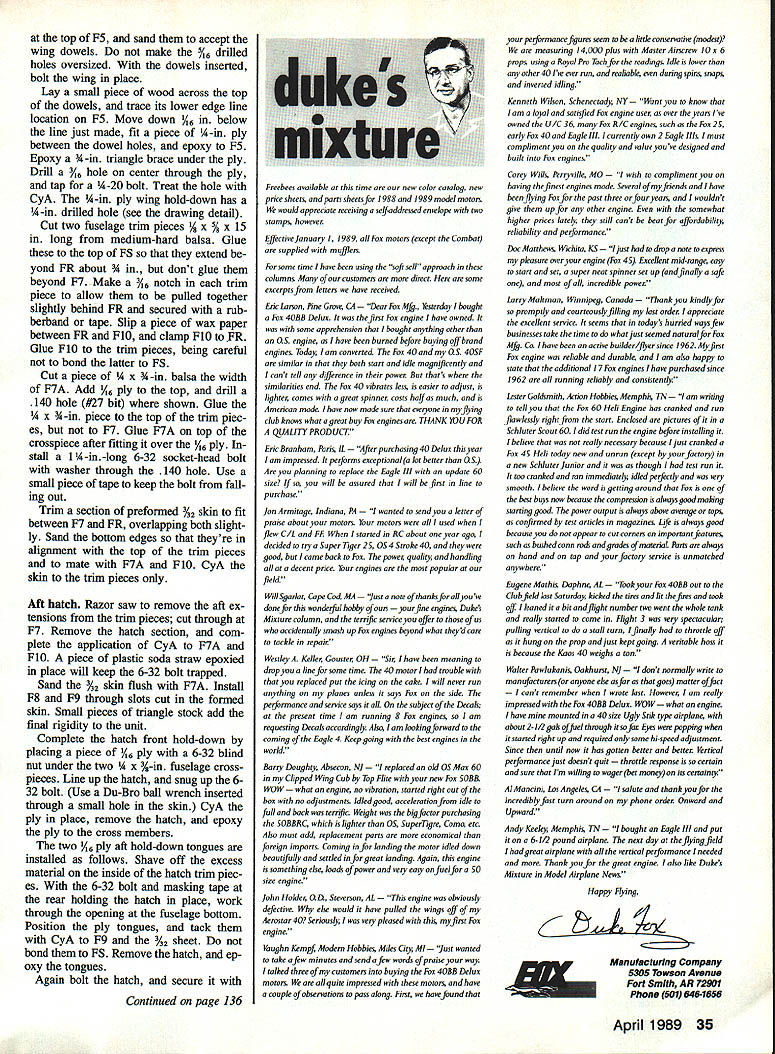
A direct descendant of my original Scale Dornier-335 design, this sport twin-engine model is much simpler to build than its predecessor. The 1962 rendition, scaled from factory drawings and photos received directly from Dornier, was powered with twin K&B .45 engines. A later version (photo in Model Aviation, October 1986) utilized two K&B .40s. As a "full house" model, the Dornier is quite complex. In contrast, the Push-Pull 240 goes together easily and was designed with basic construction methods in mind.
Since using two engines of equal size was my prime objective, achieving the correct weight and balance became the major challenge. Doing so would allow the plane to stay airborne with either engine playing dead, while the push-pull configuration would eliminate the asymmetrical thrust problems of the conventional twin-engine design.
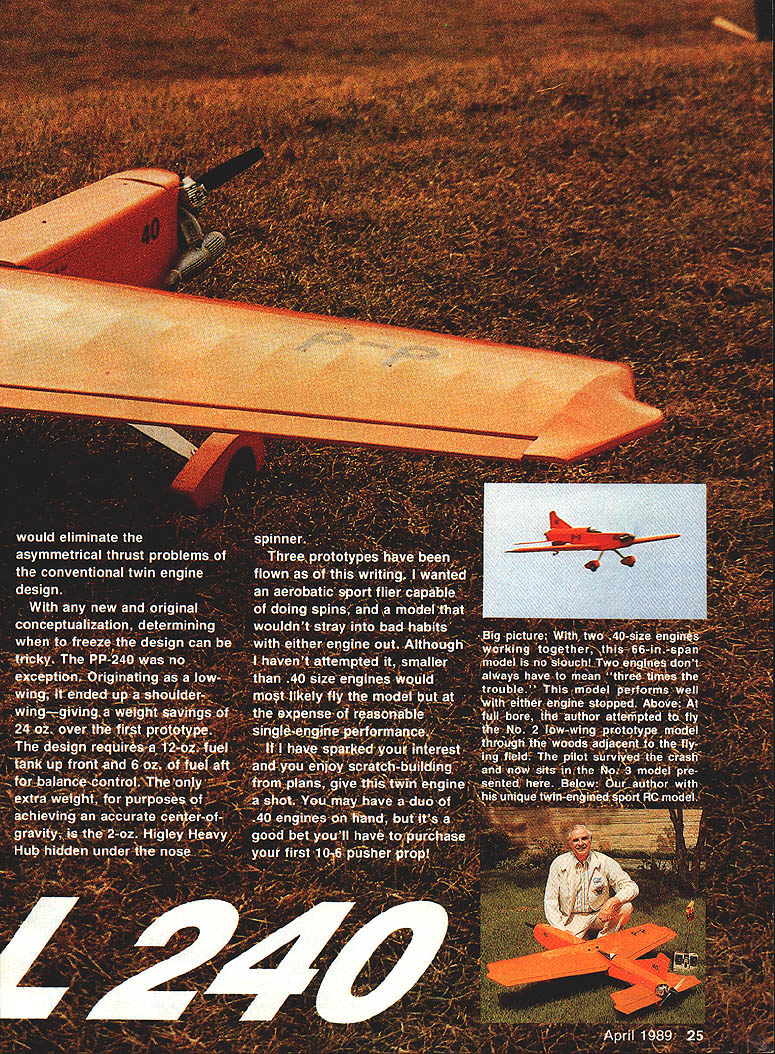
With any new and original conceptualization, determining when to freeze the design can be tricky. The PP-240 was no exception. Originating as a low-wing, it ended up a shoulder-wing—giving a weight savings of 24 oz. over the first prototype. The design requires a 12-oz. fuel tank up front and 6 oz. of fuel aft for balance control. The only extra weight, for purposes of achieving an accurate center-of-gravity, is the 2-oz. Higley Heavy Hub hidden under the nose spinner.
Three prototypes have been flown as of this writing. I wanted an aerobatic sport flier capable of doing spins, and a model that wouldn't stray into bad habits with either engine out. Although I haven't attempted it, smaller than .40-size engines would most likely fly the model but at the expense of reasonable single-engine performance.
If I have sparked your interest and you enjoy scratch-building from plans, give this twin engine a shot. You may have a duo of .40 engines on hand, but it's a good bet you'll have to purchase your first 10-6 pusher prop!
Fuselage
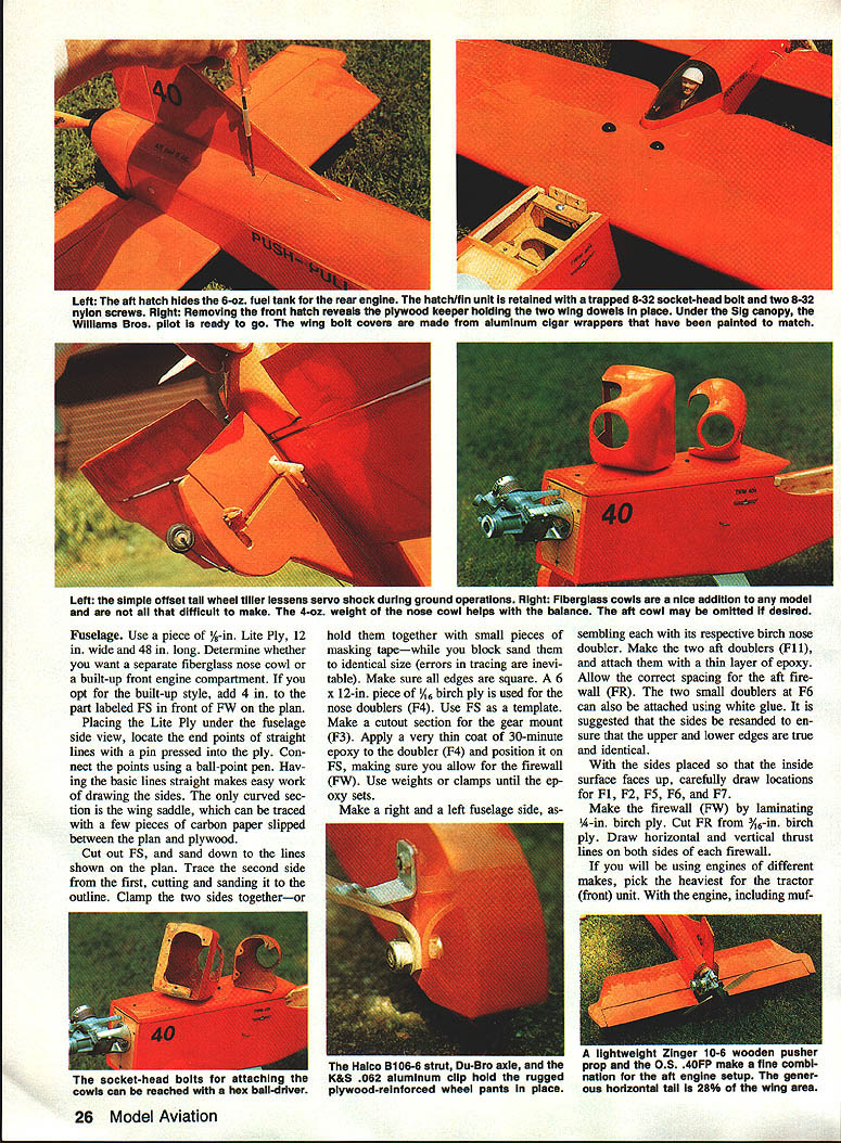
Use a piece of 1/8-in. Lite Ply, 12 in. wide and 48 in. long. Determine whether you want a separate fiberglass nose cowl or a built-up front engine compartment. If you opt for the built-up style, add 4 in. to the part labeled FS in front of FW on the plan. Placing the Lite Ply under the fuselage side view, locate the end points of straight lines with a pin pressed into the ply. Connect the points using a ball-point pen. Having the basic lines straight makes easy work of drawing the sides. The only curved section is the wing saddle, which can be traced with a few pieces of carbon paper slipped between the plan and plywood.
Cut out FS, and sand down to the lines shown on the plan. Trace the second side from the first, cutting and sanding it to the outline. Clamp the two sides together, or hold them with small pieces of masking tape, while you block sand them to identical size (errors in tracing are inevitable). Make sure all edges are square.
A 6 x 12-in. piece of 1/16-in. birch ply is used for the nose doublers (F4). Use FS as a template. Make a cutout section for the gear mount (F3). Apply a very thin coat of 30-minute epoxy to the doubler (F4) and position it on FS, making sure you allow for the firewall (FW). Use weights or clamps until the epoxy sets.
Make a right and a left fuselage side, assembling each with its respective birch nose doubler. Make the two aft doublers (F11) and attach them with a thin layer of epoxy. Allow the correct spacing for the aft firewall (FR). The two small doublers at F6 can be attached using white glue. It is suggested that the sides be re-sanded to ensure that the upper and lower edges are true and identical.
With the sides placed so that the inside surface faces up, carefully draw locations for F1, F2, F5, F6 and F7.
Make the firewall (FW) by laminating 1/8-in. birch ply. Cut FR from 3/16-in. birch ply. Draw horizontal and vertical thrust lines on both sides of each firewall.
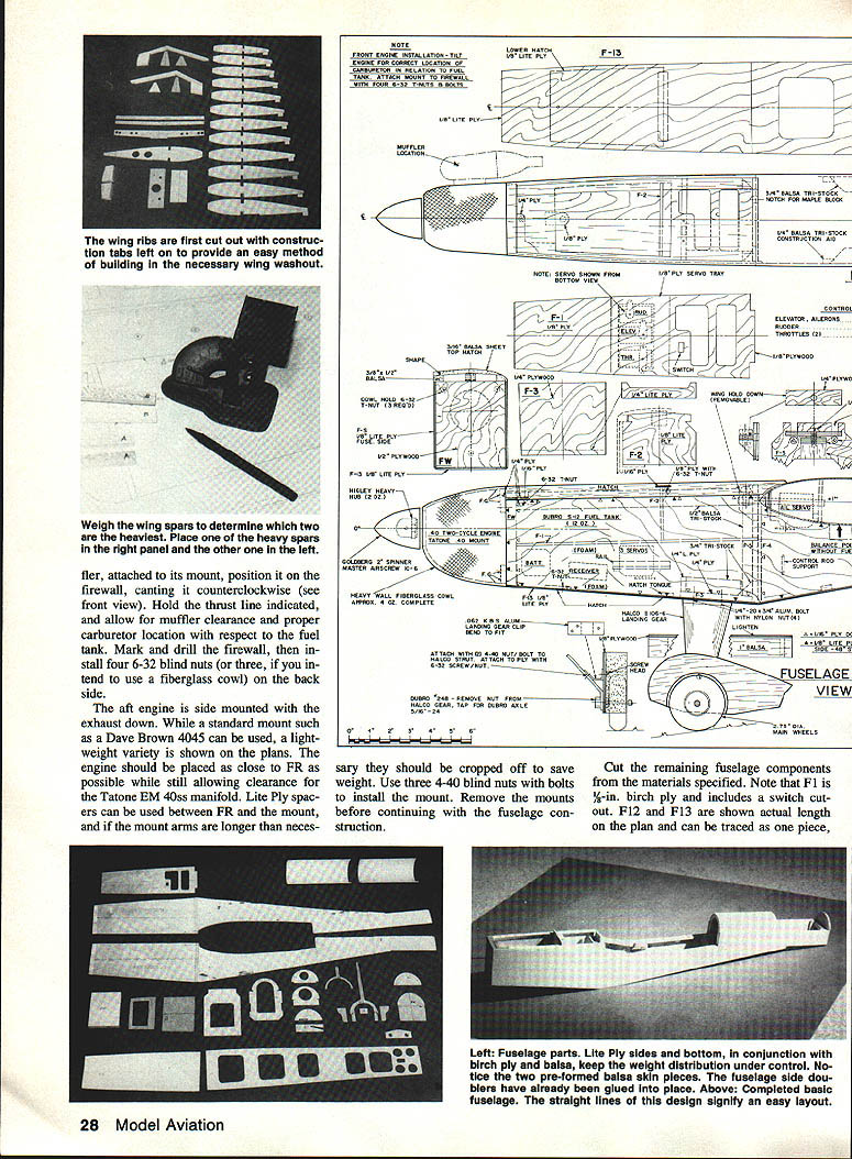
If you will be using engines of different makes, pick the heaviest for the tractor (front) unit. Weigh wing spars and determine the two heaviest. Place one heavy spar in the right panel, the other in the left. Each spar is attached in its mount position. Cant the firewall counterclockwise (see front view). Hold the thrust line indicated; allow muffler clearance and proper carburetor location with respect to the fuel tank.
Mark and drill the firewall; install four 6-32 blind nuts. If using the fiberglass cowl, mount the rear engine with the exhaust down. A standard mount such as the Dave Brown 4045 can be used. The engine should be placed as close to FR as possible while still allowing clearance for the muffler. Lite-ply spacers can be used between FR and the mount arms if longer mounts are necessary.
NOTE — FRONT ENGINE INSTALLATION: Be sure of the correct location of the carburetor in relation to the fuel tank. Attach the front engine mount to the firewall with four 1/4-32 T-nuts and bolts. Provide lower motor clearance and allow for muffler location as shown on the plans.
Make the servo tray from 1/8-in. ply. Mount the elevator and aileron servos on ply supports as indicated on the plans. Use appropriate threaded inserts and hardware for the heavy load points. Install pushrods and linkages so they operate smoothly without binding.
Fiberglass cowls are a nice addition but are difficult to make. A 4-oz. nose cowl helps balance; the aft cowl may be omitted if desired. Nose doublers are 1/16-in. birch ply; use FS as a template and cut the gear-mount section as shown. Apply a very thin coat of 30-minute epoxy to the doublers and position them, allowing for the firewall. Use weights or clamps until the epoxy sets.
The aft engine is side-mounted with the exhaust down. While a standard mount such as a Dave Brown 4045 can be used, a lightweight variety is shown on the plans. The engine should be placed as close to FR as possible while still allowing clearance for the Tatone EM 40ss manifold. Lite Ply spacers can be used between FR and the mount, and if the mount arms are longer than necessary they should be cropped off to save weight. Use three 4-40 blind nuts with bolts to install the mount. Remove the mounts before continuing with the fuselage construction.
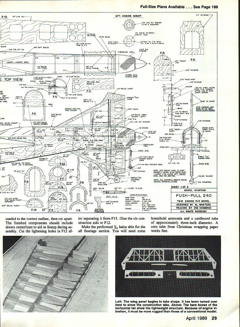
Cut the remaining fuselage components from the materials specified. Note that F1 is 3/8-in. birch ply and includes a switch cutout. F12 and F13 are shown actual length on the plan and can be traced as one piece, sanded to the correct outline, then cut apart. The finished components should include drawn centerlines to aid in lineup during assembly. Cut the lightening holes in F12 after separating it from F13. Glue the six construction aids to F12.
Make the preformed 3/32-in. balsa skin for the aft fuselage section. You will need some household ammonia and a cardboard tube of approximately three-inch diameter. A core tube from Christmas wrapping paper works fine. Blot the wood with a paper towel and wrap it around the tube, using masking tape to hold it in place. Set the balsa skin aside, and allow it to air dry thoroughly.
Begin assembling the fuselage over the top view of the plan. Support the sides upright, and glue the firewall in place using F5 as a spacer. Use white glue since it will allow more time for lining everything up. Place a weight such as an ordinary brick on the top front edges of the fuselage sides, and clamp FW in place. Do not pull the aft fuselage section together at this time. The lower fuselage line forward of F5 is straight so the weight will keep the setup square on the work surface until the glue sets.
Attach FR using white glue or 10-minute epoxy with the aid of a clamp. Hold the sides together, and attach F6 with CyA. Add the two 1/4 x 3/8-in. crosspieces that fit into F11. Check the position of F5, and tack with CyA.
Make relief notches in F1 to clear the blind nuts on the back side of FW. Force F1 into position, where it will aid in correcting any misalignment of the front firewall and F5, and attach with CyA. Install 3/16 x 1/4-in. hardwood servo rails, and make a servo tray from 1/8-in. ply to fit. After gluing F3 into place, set the fuselage aside—you'll be completing it later—and proceed to the wing.
Wing
Trace and cut one set of ribs, using them as a pattern to make a second set. Pin the ribs in pairs, and draw the chord lines shown on both sides of each rib. Cut the dihedral braces and draw the two centers indicated on both sides of the leading edge brace. Cover the wing plan with wax paper or plastic film before proceeding.
Cut four straight 1/4 x 1/2-in. balsa spars to length. At this point weigh the four pieces and distribute the spars to avoid using the two heaviest spars in the same panel.
Glue the lower ply dihedral brace to one of the spar halves, and position the spar over the plan, securing it with pins or weights. Position ribs 1 through 12 on the spar, making sure the construction tabs are resting on the work surface. The 1/4 x 3/8-in. trailing edge and the 1/2 x 1/2-in. leading edge are pinned in place on the ribs to aid in the lineup. The space between ribs 1 and 2 provides for the leading edge brace, which will be slipped in later.
After making sure that all ribs are perpendicular to the work surface, CyA the ribs to the spar, leading edge, and trailing edge. Fit the upper spar, and glue it in place. Block sand the upper surface of the trailing edge slightly to follow the rib contours.
Select four sheets of 3/32-in. balsa (2-in. stock) for the upper and lower trailing edge skins. Check their weights, using the two heaviest on opposite panels. Hold a metal yardstick edgewise across the ribs at the inboard sheet edge to be certain that the sheet will be straight when attached to the ribs. A high rib can be carefully sanded down, but don't worry about a low rib at this point.
Turn the wing over. Using a piece of wood such as a ruler, press the wing downward to contact the 3/32 sheet as you bond the ribs with CyA. Work about three ribs at a time, starting at rib 1 and skipping any low ribs. Maintaining a straight sheet line without waves is more important than gluing every rib, and a chip of 1/4-in. triangle stock can be used to support the skin at a low rib. The cap strips added later will hide a multitude of construction errors.
Build the wing tip, and attach it to rib 12. Center the tip on the rib chord line at the leading edge and on the 1/4 x 3/8-in. trailing edge. The balsa filler at the trailing edge tip will allow for block sanding to fit the contours of the 3/32 sheet and aileron. Attach the tip webs, which will be final sanded after the rib caps are in place. Add the four hinge supports and the vertical-grain 3/32 spar webs between ribs 3 and 12.
Fit rib 1F into place. With the panel one inch off the work surface at rib 12, set 1F perpendicular to the work surface; glue it to the trailing edge and the spar notch while tack gluing it to the leading edge. Note that 1F is shown at actual length on the plan and that it reaches the leading edge strip. Allow space in the spar notches in which to fit the dihedral brace and the mating spars later. Set the panel aside, and construct the opposite panel in a similar manner.
With the completed second panel on the work surface, fit the two panels together. Elevate the first panel 2 in. as per the drawing, and push the lower spars together until they butt. Slightly bevel the spar end to obtain a good fit. The upper dihedral brace is slipped in alongside the upper spars and clamped, using at least two clamps on each side of the wing centerline. Make sure the 1/4-in. dihedral brace fits flush with or slightly below the spars, as sanding down later will be difficult.
Add the leading edge ply brace, clamping it in the same manner. Rib 1F will have to be razor sawed 1/8 in. shorter. Make sure the horizontal centerline of the leading edge dihedral brace is located correctly on ribs 1 and 2 on both panels.
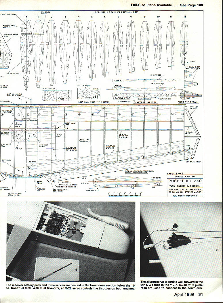
The bottom edge of the servo mount section is located 5/8 in. back from the leading edge. The servo tray is removable for maintenance. Install the aileron servos and check linkage with the aileron horn travel shown on the plan. Fit the 1/8-in. ply leading edge sheeting with temporary pins and glue with thin CyA. Sand the sheeting to the rib caps. Cut and fit the ailerons. Fit piano hinges and use a bead of CyA on each side of the hinge after installation.
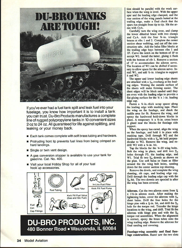
Cover the wing with silkspan and dope or your favorite covering material. For this model 0.7-oz. silkspan was used. After the covering is finished, install the pushrods, terminal blocks, and servo leads. Balance the wing by adding weight at the tip if necessary. Mount the wing to the fuselage using the two 3/16 x 1-1/4-in. bolts in the wing bolt plate as shown on the plan.
Alignment should be parallel with the work surface when the wing is level. With the upper spar and the leading edge clamped, and the rear section of the wing panels butted at the trailing edge, make a final check that the spars run straight from tip to tip. Hit the arcs with CyA.
Carefully turn the wing over, and clamp the lower dihedral brace with two clamps and CyA. Add the four 3/4-in. triangle braces at ribs 1 and 2. Complete the center section shear webbing, and cut off the construction tabs. Add the balsa filler blocks at the trailing edge bays between ribs 1 and 1F. Carve the notch on the bottom of 1F to accept W2. Install W2, gluing it flush with the bottom of rib 1. Remove a section of 1F to accommodate the aileron servo. The location of W1 can be shifted if necessary to allow space for the aileron servo. Install W1, and add 1/2-in. triangles to support it and W2.
The upper and lower leading edge sheets are attached with a 1/16-in. overhang at the leading edges. Wetting the outside surface of the sheets will make forming easier. The sheet edges will be block sanded until they are even with the leading edge to provide a flat gluing surface for the 1/4 x 1-in. leading edge cap.
Fasten a 1/4-in.-thick scrap spacer along the leading edge with masking tape. Place the wing on the fuselage, and check the saddle area for fit. Remove the wing, and epoxy the hardwood hold-down blocks in place. A temporary 1/4 x 1/2-in. cross brace is glued near the blocks for fuselage side support.
When the epoxy has cured, align the wing on the fuselage, and hold it in place with masking tape. Drill through W2 and the hardwood blocks with a 3/16-in. bit perpendicular to W2. Remove the wing, and redrill W2 with a 1/4-in. bit.
Tap the blocks for the 1/4-20 wing bolts. Bolt the wing in place, and drill two 5/16-in. holes through FS, the leading edge, and W1. Trial fit two 3/16-in. dowels as shown on the plan. Use soft balsa or foam as filler around the two wing bolt holes, sanding down for the center section top sheeting.
Remove the dowels, and complete the wing sheeting, rib caps, and leading edge cap. Drill through the leading edge cap with the 3/16-in. bit. The two dowels are epoxied in after the wing has been covered.
Ailerons
Cut the two aileron cores from 3/8 x 1-1/2-in. aileron stock. After making the lightening holes, cover the ailerons with 1/16-in. sheet balsa. Drill the four holes for the hinge pins with a 5/64-in. bit, and drill the 3/32-in. hole for the torque rod. Transfer the hinge locations to the wing, and drill. Trial fit the ailerons with hinge pins and with the torque rod assemblies. When alignment is correct, epoxy the brass tubes onto the wing trailing edge. Reinforce the ailerons for final sanding and covering.
Fuselage-wing assembly and final fuselage construction
Razor saw the two slots in the top fuselage longerons for the wing bolt plates. Make sure the slots are positioned so the wing will sit down on the fuselage properly. Install the front wing bolt plate and the two 3/16 x 1-1/4-in. bolts through W2 into blind nuts in the front plate. Fit the rear bolt plate and drill for the 1/4-20 bolts. Install the bolt assemblies and fit the wing. Check dihedral and incidence. Add fillets if desired. Install servos and run control linkages.
At the top of F5, sand them to accept the wing dowels. Do not make the 5/16 drilled holes oversized. With the dowels inserted, bolt the wing in place.
Lay a small piece of wood across the top of the dowels, and trace its lower edge line location on F5. Move down 1/8 in. below the line just made, fit a piece of 1/4-in. ply between the dowel holes, and epoxy to F5. Epoxy a 3/4-in. triangle brace under the ply. Drill a 3/16-in. hole on center through the ply, and tap for a 1/4-20 bolt. Treat the hole with CyA. The 1/4-in. ply wing hold-down has a 3/4-in. drilled hole (see the drawing detail).
Cut two fuselage hatch pieces 3/4 x 5 x 15 in. long from medium-hard balsa. Glue these to the top of F5 so that they extend beyond FR about 3/4 in., but don't glue them beyond F7. Make a 3/8-in. notch in each trim piece to allow them to be pulled together slightly behind FR and secured with a rubberband or tape. Slip a piece of wax paper between FR and F10, and clamp F10 to FR. Glue F10 to the trim pieces, being careful not to bond the latter to F5.
Cut a piece of 1/4 x 1/4-in. balsa the width of F7A. Add 1/8 ply to the top, and drill a 1/4-in. hole (#27 bit) where shown. Glue this 1/4 x 3/4-in. piece to the top of the trim pieces, but not to F7. Glue F7A on top of the crosspiece after fitting it over the 1/4 ply. Install a 1-1/4-in.-long 6-32 socket-head bolt with washer through the 1/4 hole. Use a small piece of tape to keep the bolt from falling out.
Trim a section of preformed 3/32-in. skin to fit between F7 and FR, overlapping both slightly. Sand the bottom edges so that they're in alignment with the top of the trim pieces and to mate with F7A and F10. CyA the skin to the trim pieces only.
Aft hatch: Razor saw to remove the aft extensions from the trim pieces; cut through at F7. Remove the hatch section, and complete the application of CyA to F7A and F10. A piece of plastic soda straw epoxied in place will keep the 6-32 bolt trapped.
Sand the 3/32-in. skin flush with F7A. Install F8 and F9 through slots cut in the formed skin. Small pieces of triangle stock add the final rigidity to the unit.
Complete the hatch front hold-down by placing a piece of 1/4-in. ply with a 6-32 blind nut under the two 1/4 x 3/4-in. fuselage crosspieces. Line up the hatch, and snug up the 6-32 bolt. (Use a Du-Bro ball wrench inserted through a small hole in the skin.) CyA the ply in place, remove the hatch, and epoxy the ply to the cross members.
The two 1/2-in. ply aft hold-down tongues are installed as follows. Shave off the excess material on the inside of the hatch trim pieces. With the 6-32 bolt and masking tape at the rear holding the hatch in place, work through the opening at the fuselage bottom. Position the ply tongues, and tack them with CyA to F9 and the 3/32-in. sheet. Do not bond them to F5. Remove the hatch, and epoxy the tongues.
Again bolt the hatch, and secure it with masking tape at the rear. Drill through the sides and tongues with a #29 bit (.136), and tap for 8-32 nylon screws. Replace and fit the hatch. Sand the 3/32 skin flush with FR. Fit the forward section of the formed sheet, and glue it in place. With the hatch in place, shave and sand the trim pieces to shape from F6 aft to FS.
Cowls
The nose cowl adds needed weight for attaining correct center-of-gravity, but the aft cowl is merely cosmetic. The "lost foam" method can be used to make the fiberglass cowls. Styrofoam forms are made undersized to allow for the cowl wall thickness. Use batches of Hobbypoxy 2 with four layers of 6-oz. cloth strips for the nose cowl; the aft cowl takes only one layer of the same size strips. Add a final layer of 2-oz. cloth to both units.
After the epoxy has set, gouge out the foam and use acetone to remove the residue. The ply cowl mounts are installed last with epoxy and strips of fiberglass cloth. The nose cowl should have a final weight of 4 oz. Use a hex ball-driver to reach the hidden socket-head bolts.
If you use extended sides (FS) and shaped balsa blocks instead of the glass nose cowl, you may need to add nose weight to correct the center-of-gravity.
Empennage
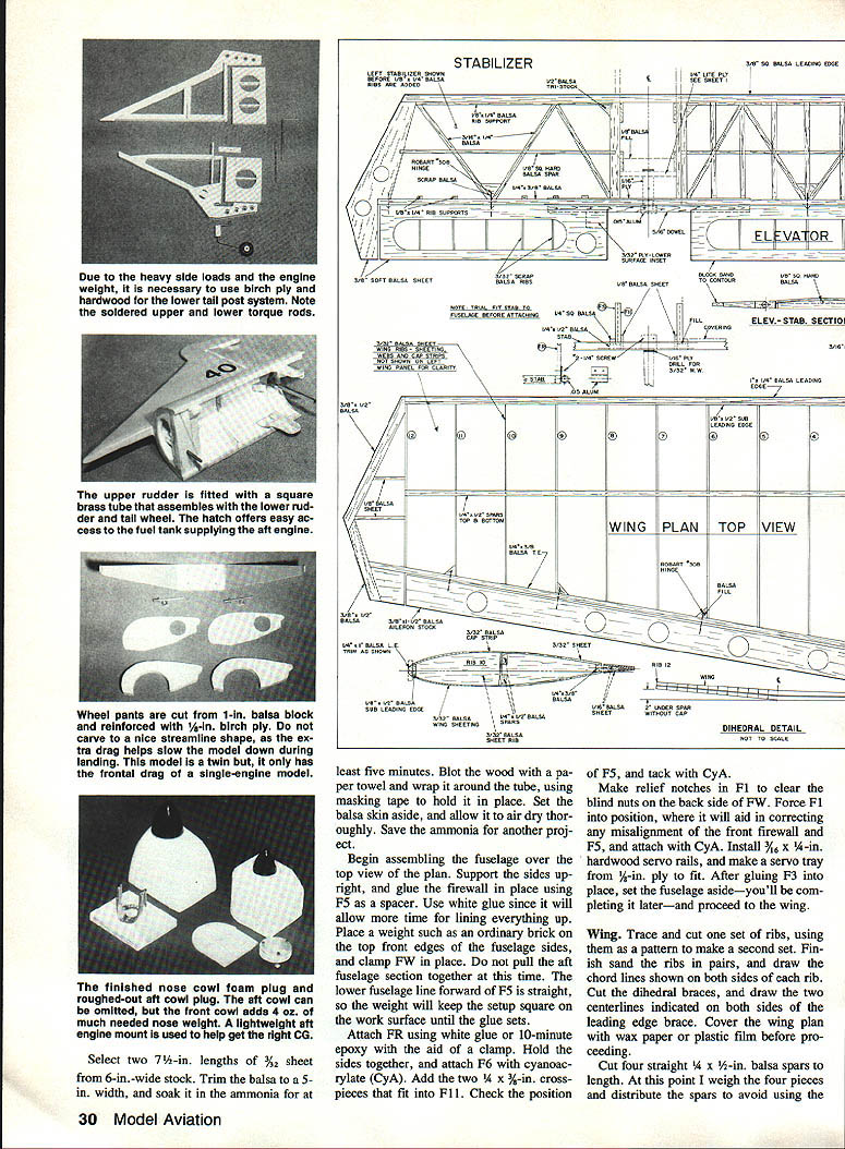
It's important to build the stabilizer light and strong, as the aft engine is right there trying to shake it apart! Build the main frame flat over the plan, protected with wax paper. Notch the tip pieces for the 1/8-in.-sq. hard balsa spar. Add the 10 rib supports and hinge blocks. Don't forget the 1/16-ply trailing edge doubler.
Trial fit the frame to the fuselage. Position the 1/4-in.-sq. balsa inboard ribs to hug the fuselage sides, sanding the ribs to the appropriate contour. This procedure allows the unit to be covered prior to attachment to the fuselage.
Add the remaining ribs, and fit in the four 1/8-in. vertical-grain braces, which will be epoxied in place after the stabilizer has been covered and attached.
Assemble the elevators to the 3/16-in. dowel, and block sand to shape. The .015-in. aluminum support is formed around the dowel.
Build the upper and lower fins with their associated rudders. The upper rudder has a groove in its lower edge to accept the 3/32-in. wire torque rod. Fit the upper fin in place over F8 and F9.
The lower fin tail post, of 1/8-in. birch ply, is predrilled with a 1/8-in. bit for the hinge point. Make the lower fin, including the 1/16-ply bearing piece with the 3/32-in. hole for the lower torque rod. The trailing edge of the fin is clamped and glued after the hardwood block with the formed tail wheel wire has been glued in place. Add the soft balsa filler, and set aside.
#### Rudder torque rods
To make the upper torque rod, start by cutting two pieces of 3/32-in. music wire, making one 2-1/2 in. and the second 4-1/2 in. long. Make a 90° bend 1 in. from the end on each. Solder a 1/2-in. section of K&S .125-in.-sq. brass tubing so that it's even with the end of the 3/32-in. leg. Allow no solder on the outside of the brass part. Tinning the wire first and then sweating the brass to the wire makes a neat job.
Solder a 1/2-in. piece of .125-in.-sq. brass tubing onto the end of the 1/2-in. leg. A 2-1/2-in. piece of .156-in.-sq. brass tubing is slipped over the .125 tubing for 1/2 in. and soldered.
Lay the upper and lower torque rods on a flat board in their relative positions. Assemble the lower tube into the upper tube, but telescope the mating parts only one-fourth of an inch.
Tackle the upper wire assembly with the soldering iron, remelting the upper joints and applying very light pressure so that both 90° arms are resting on the flat surface. The arms will now be lined up. If the parts are assembled more than the specified 1/4 in. before remelting for lineup, you risk fusing the whole assembly and making it unusable. Telescope the two parts, checking for ease of fit and dimensions.
Assembling and covering
Finish the fuselage sides and the top sheeting. Do not add the bottom sheeting at this time. Apply the 1/16-in. sheeting to the bottom of the fuse only on the engine pod area to give additional strength for mounting the engines. Install the servo trays, and fit the radio gear. Install the landing gear and wheel pants per the drawings.
Fit the top hatch and canopy area, then seal the front fuel tank area with epoxy. F1 and F2 provide a fuel-tight compartment to protect the electronics carried below. Assemble the controls, supporting them where necessary. Add triangle stock, and close up the compartment with F13. Cut the lower hatch, and provide for retaining. Attach the Halco strut with four 4-40 aluminum bolts and plastic nuts.
The wheel pants are sawed from one 4 x 12-in. balsa block 1 in. thick. Reinforce them with 1/8-in. birch ply. Resist the temptation to carve and sand the wheel pants to a nice, streamlined shape. They need a certain heft in order to contribute drag at landing time. Remember that although there are two engines at idle, the frontal drag area is that of a single engine.
After final sanding and vacuuming free of dust, cover individual parts with your favorite material. Coat both firewalls with epoxy inside and out.
When covering the stabilizer, leave the bottom center section open. Position the stab and attach with CyA, checking alignment carefully. Pass the lower torque rod through the 1/16-ply bearing. Fit the lower fin into the slot in F12, and clamp the lower tail post to the 1/4-in. Lite Ply fuselage cross brace. Square up and epoxy the fin leading edge on the inside of the fuselage. Attach the 1/4-in. ply lower tail post to the 1/4-in. Lite Ply cross brace using CyA. Glue the four vertical-grain 1/4-in. braces to the stabilizer and fuselage sides. Close up the stab center section.
Push the lower rudder over the torque rod and epoxied hinge point. (Make sure you treat the center of the hinge point with petroleum jelly if you expect hinge action after the epoxy cures!)
Angle the upper torque rod into position through its ply bearing, and join the two torque rods. Fit the aft hatch in place, and bolt. Assemble the upper rudder with its hinge point. Line up the two rudders, and epoxy the upper torque rod into the groove on the bottom of the rudder.
Install the elevators, and attach the .015-in. aluminum support to the aft firewall with two No. 2 screws.
Secure the tail wheel tiller loop to the lower rudder with a small rubberband bound as tight as possible. The tail wheel is offset and the rudder pushrod is undersize to minimize servo shock.
With the engines in place, pipe up the fuel systems, using pressure on both. Use a Hughes Heavy Hub and a Master Airscrew 10-6 prop up front, and the lighter Zinger 10-6 wood pusher prop at the rear. This combination will give an extra 3 oz. up front where it counts.
Install the electronics, feeding the antennae back through the upper lengthening holes and snaking them out the three holes on the left side just above the stabilizer.
Flying
A single servo controls both throttles. By using the Du-Bro EZ connector cable arrangement at the servo, the throttle linkage can be independently adjusted. Set the front engine with a reliable idle at the high-trim position. Low trim should cut the engine. Kill the front engine, and set up the aft engine in the same manner.
Setting up the engines in this manner makes it unlikely that both can be cut off at precisely the same time. However, this presents no problem, since if one engine should fail on final approach a go-around on single engine is readily made if desired. It's unnecessary to synchronize the engines; just have both running well.
It's important that the aft fuel tank be carried as high as possible within the tail section. I use a 1/8-in.-thick foam under the tank. Since an engine in pusher configuration does not have ram carburetor air, the tank location in relation to the needle valve is critical in order to avoid early starvation as the fuel level lowers. A small sheet metal scoop was attached to direct ram air into the carburetor throat. Although this worked efficiently, carrying the tank higher is much simpler and equally effective. Keep it tight.
Note that the rear tank chunk is installed in the forward position. Having used the chunk in both directions with both pushers, I've found that the forward installation is not only satisfactory but requires much less fuel inline.
As with all aircraft having pusher propellers, special precautions must be observed to prevent debris from going through the prop. The author owned a full-scale Lake Amphibian pusher for many years, and found that protecting the propeller from loose nuts and bolts (and fishing rods) was always a major concern. A twin engine with a push-pull arrangement is especially vulnerable. The front prop can kick up stones, starter cables, wiping cloths, etc., and promptly present them to the rear prop for digestion!
Flying a twin pusher also requires special watchfulness. One flight of the Push-Pull 240 was a near-fiasco. Immediately after takeoff the carburetor on the aft engine became loose and moved into the pusher prop, which promptly self-destructed. The engine, a full bore and extremely unbalanced, all but tore itself from the firewall—before fuel starvation saved the day! The whole scenario lasted about three or four seconds, and pilot Ray Doan brought the ship back on single engine. A thorough preflight check would have spared the pusher prop.
The main thing to remember, to get the Push-Pull smoothly aloft, is to advance the throttle(s) steadily during takeoff. Ground control will be positive with no torque correction required. Climbout will be solid, and as you watch her slice through the ether the sound of those twin .40s is something else!
Transcribed from original scans by AI. Minor OCR errors may remain.

