


Pussycat
Bob Benjamin
The popularity of electric flight has been increasing as more modelers discover its advantages: cleanliness, absence of engine vibration, freedom from starting problems, and the lack of noise to annoy neighbors and jeopardize flying-site use.
The Pussycat is the result of an effort to improve the situation for trainers and easy-flying sport models. Stable, lightly loaded electric sailplanes and old-timers do well for beginners flying solo (they will fly "hands off" for extended periods), but they are hard to manage in windy weather.
Several kits advertised as electric trainers will work, but they are often designed around inexpensive six- and seven-cell motors. Consequently they are too small and underpowered for good performance in wind.
This model is for the beginner who has the help of an instructor, or for someone who has soloed a glider and wants to practice real takeoffs and landings. It is also for the electric flier who wants an easy-flying design that can be flown safely without having to wait for a calm evening, and that is fun to look at as well as to fly.
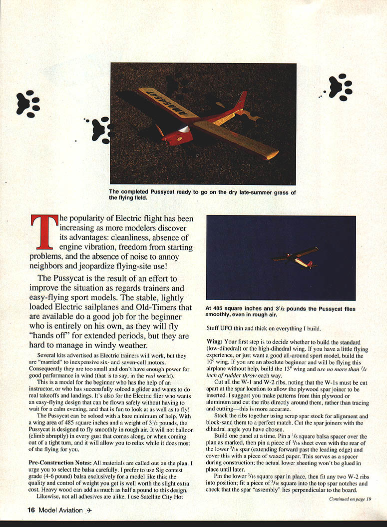
The Pussycat can be soloed with a bare minimum of help. With a wing area of 485 square inches and a weight of 3-1/2 pounds, it is designed to fly smoothly in rough air. It will not balloon in every gust or when coming out of a tight turn, and it will allow you to relax while it does most of the flying for you.
Pre-Construction Notes
All materials are called out on the plan. Select balsa carefully. Sig contest grade (4–6 pound) balsa is recommended for a model like this; the quality and control of weight you get is well worth the slight extra cost. Heavy wood can add as much as half a pound to the design.
Not all adhesives are alike. Satellite City Hot Stuff (UFO) thin and thick work well on everything in this model.
Wing
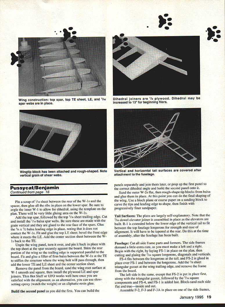
Your first step is to decide whether to build the standard (10°) or the high-dihedral (13°) wing. If you have some flying experience or want a good all-around sport model, build the 10° wing. If you are an absolute beginner and will be flying without help, build the 13° wing and use no more than 1/4 inch of rudder throw.
- Cut all W-1 and W-2 ribs, noting that the W-1s must be cut apart at the spar location to allow the plywood spar joiner to be inserted. Make templates from thin plywood or aluminum and cut ribs directly around them for accuracy.
- Stack ribs with scrap spar stock for alignment and block-sand them to a perfect match. Cut spar joiners with the chosen dihedral angle.
- Build one panel at a time. Pin a 1/8" square balsa spacer over the plan as marked, then pin a piece of 1/16" sheet even with the rear of the lower 7/16" spar (extending forward past the leading edge) and cover with waxed paper. This spacer is used during construction; the actual lower sheeting won't be glued until later.
- Pin the lower 3/32" square spar in place; fit the two W-2 ribs. Fit the top spar and check that the spar assembly lies perpendicular to the board.
- Pin a scrap 1/16" sheet between the rear W-1s as a spacer, glue the ribs in place and be sure the inner W-1 allows the correct dihedral using the template on the plan. There will be very little gluing area for the W-1s.
- Add the top spar followed by the top 1/16" sheet at the trailing edge. Cut and install 1/16" balsa spar webs; be sure the grain is vertical and glued to the rear face of the spars.
- Glue a 1/4" x 1/2" balsa leading edge in place; it does not contact the W-1. Fit and glue the top leading-edge sheet, beveling the front edge to meet the leading edge.
- Add center-section sheeting between the W-1s back of the trailing edge. Unpin the wing panel and turn it over; pin back in place and press the top sheet and spar securely against the board. Shim the rear portion so the wing trailing edge is supported parallel to the board.
- Fit and glue firm balsa filler between the W-1s and the trailing edge to stiffen the structure where the wing bolt will pass through. Add the lower trailing edge and leading-edge center-section sheeting.
- Remove the panel from the board and sand the wing root surface at the W-1 smooth and square. Install the plywood leading-edge spar joiners. Thin Hot Stuff (UFO) works well; once satisfied with alignment, slow-setting epoxy is an alternative (watch the weight). Aliphatic-resin glue may also be used.
- Build the second panel the same as the first. You can build the tip panels separately and join later, or prop up the first panel to the correct dihedral and build the second panel onto it.
- Sand the outer W-2s flat and rough-shape tip blocks from balsa; glue them in place and do final shaping later. Use a block plane and coarse-paper sanding block to carve the tip leading-edge shape, finishing with progressively finer sandpaper.
Tail Surfaces
The plans are largely self-explanatory. Note that the 3/16" dowel elevator joiner is assembled in place as the elevators are built. The elevators are built over R-1 and extend below the lower edge; the vertical tail will fit between the top fuselage longerons. The R-1 root will have to be tapered at the rear—do this at final assembly after the fuselage is built.
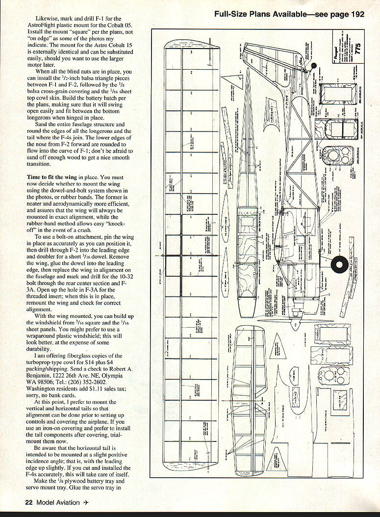
Fuselage
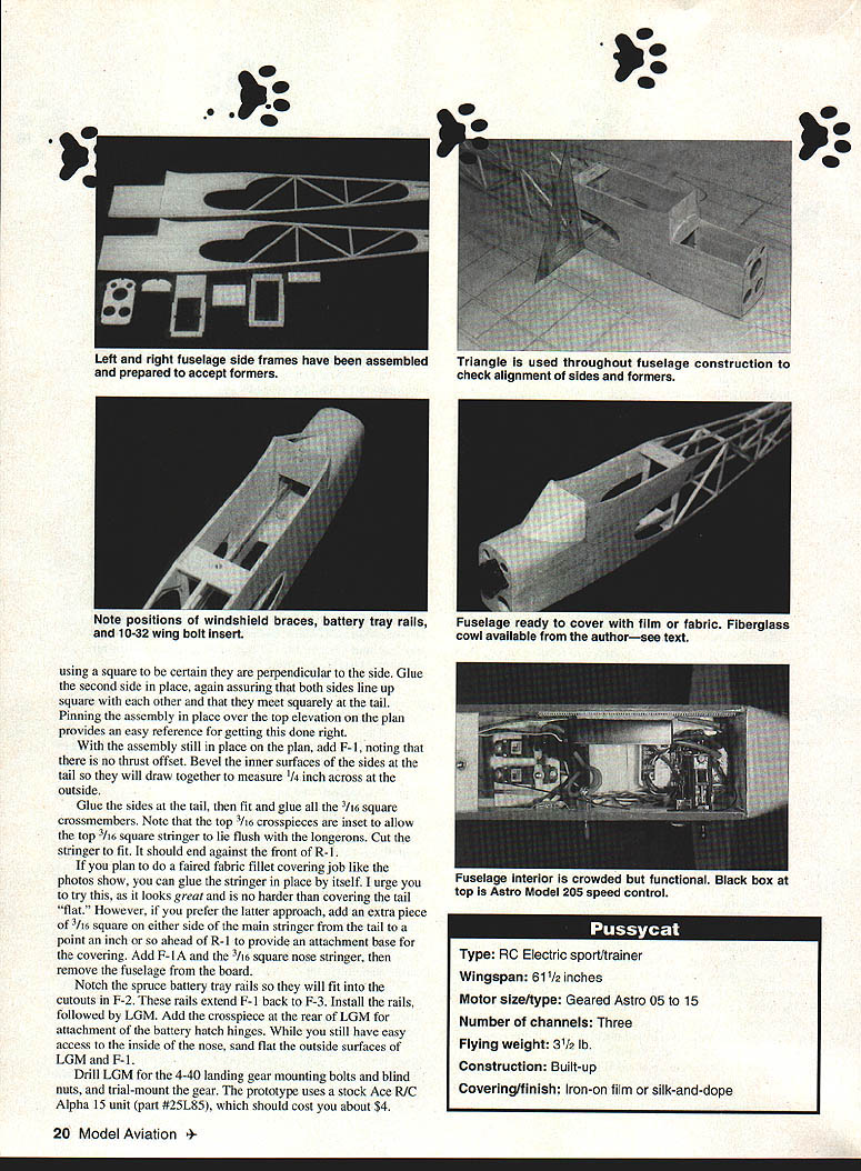
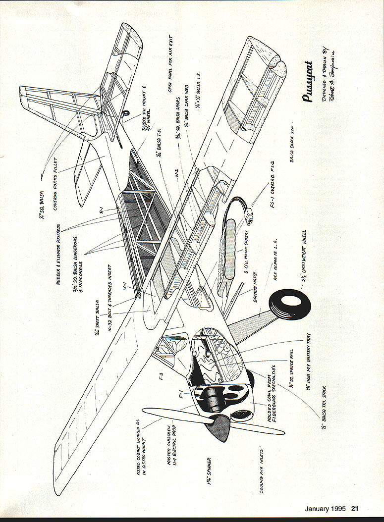
- Cut all side-frame parts and formers. Make a left and a right side carefully. Begin with the right: lay FS-1 in place on the plan, then cut and glue the 3/16" square longerons, diagonals and verticals. FS-4 fits between the longerons at the tail, and FS-2 is glued in place over FS-1 and between the longerons. Add the 1/8" sheet triangular gusset at the wing trailing edge, and remove the frame from the board.
- Build the left side similarly, except FS-2 is put in place first, along with the triangular gusset, followed by the 3/16" square components and FS-4, with FS-1 added last. Block-sand each side flat and true—inside and out.
- Assemble F-2, F-3 and F-3A in place on one side frame, then glue in F-4 and F-5 followed by the firewall and F-1. Use a square to keep things aligned. Add the bottom longeron and bottom vertical cross pieces.
- Glue the other side frame in place, check alignment, then add the top longerons and top verticals. Pin the assembly to the plan to make sure all is fair and square.
- Bevel the inner surfaces of the sides at the tail so they will draw together to measure 1/4" across at the outside. Glue the sides at the tail, then fit and glue all 3/16" square crossmembers. Note the top 3/16" crosspieces are inset to allow the top 3/16" square stringer to lie flush with the longerons. Cut the stringer to fit. It should end against the front of R-1.
- If you plan to faired-fillet cover (recommended), glue only the main stringer in place. If you prefer a flat tail before covering, add an extra piece of 3/16" square on either side of the main stringer from the tail to about an inch ahead of R-1 to provide an attachment base for the covering.
- Add F-1A and the 3/16" square nose stringer, then remove the fuselage from the board.
- Notch the spruce battery tray rails so they fit into the cutouts in F-2. These rails extend F-1 back to F-3. Install the rails, followed by LGM. Add the crosspiece at the rear of LGM for attachment of the battery hatch hinges. While you still have easy access to the inside of the nose, sand flat the outside surfaces of LGM and F-1.
- Drill LGM for the 4-40 landing gear mounting bolts and blind nuts, and trial-mount the gear. The prototype uses a stock Ace R/C Alpha 15 unit (part #25L85).
Place and mount the rudder and elevator servos, and install rudder and elevator horns and control linkages of your choice. The author used Du-Bro Lazer Locks for a tight, slop-free installation with minimal temperature-related distortion.
Add short lengths of 1/4" square spruce above the battery tray at F-1 to hold the front end of the tray in place, drill and install screws per the plan, and trial-fit the motor battery. Add the 3/16" square cowl mounting flanges at F-1, then trim the cowl to fit and trial-mount it with the motor in place to get a good fit with the spinner.
Install and test the rest of the radio and power system so any cutting and adjusting will be done before the covering is in place.
Covering
Use whatever covering works best for you: iron-on film or traditional silk-and-dope will both work on the Pussycat.
If you want a faired fabric fillet where the fuselage and vertical tail meet (recommended), follow this procedure:
- Cover the horizontal tail first, then the fuselage bottom.
- Lay the fuselage (with the vertical fin permanently attached) on its side and cut a piece of material for each side that covers the entire side from F-1 to the tail (including the fin), leaving generous overhang.
- Trim a slot so the material fits exactly around the root of the horizontal tail, and iron the covering in place at that point.
- Go along the entire vertical tail trailing edge and gently pull tight at F-1. Iron down along the rear six inches or so of the lower longeron and at the top of the fin, pulling tight gently and smoothing as you go.
- Pull the covering as tight as you dare across the curve where the fin leading edge and dorsal fin come together, and start ironing down along the dorsal stringer and all remaining edges.
- Repeat on the other side, keeping a wide overlap along top edges. Trim with care, reseal all edges, and then shrink everything.
If careful, this will remove wrinkles and give a covering job to be proud of.
Flying
With all covering and trim in place, do a final assembly and shift components as necessary for balance. The design does not tend to be tail heavy; the prototype balances perfectly with the equipment mounted as shown in the photos. Do not fly until the airplane balances—move components until it hangs level when suspended beneath the wing root in line with the balance location shown.
Power recommendations:
- The model will fly on any of the better geared "can" type ferrite motors and a seven-cell battery if built light and equipped with the correct prop, but it was designed for a geared Astro Cobalt 05.
- The optimum combination tested with that motor is an eight-cell, 1200–1700 mAh battery with a Master Airscrew 11 x 7 Electric Series prop. With this setup, takeoffs from mowed grass require about fifty feet and it maintains level flight at about half power.
- For more aerobatic performance, substitute a geared Astro Cobalt 15 on 12 cells.
About chargers and cells:
- For many years a seven-cell battery was considered standard because common inexpensive 12 V DC chargers would not handle higher cell counts.
- There is nothing magic about seven cells for the Astro Cobalt 05. Better-quality chargers handle higher cell counts and are only slightly more expensive. Example: the Astro Flight Model 110XL works with up to 16 cells, features peak detection, and retails well under $100.
Aerobatics and dihedral:
- The Pussycat will do basic aerobatics, but you must get "on step" for clean loops and rolls from level flight.
- Increasing wing dihedral from 10° to 13° markedly increases roll rate but makes the airplane bounce more in wind. The 13° wing with very limited rudder throw (about 1/4" each way) provides a more stable model for a beginner flying without help, again at the expense of increased bounciness in rough air.
Seeing the airplane fly is very helpful. For $9.95 plus $3 shipping and insurance, you can buy a 10-minute broadcast-quality video describing the Pussycat prototype. It features closeups, an honest hands-off takeoff and flyby, and several flight sequences with the airplane "turned loose" against a background of high clouds.
Order "The Pussycat Trainer" from: Videoland Productions 805 College Street Lacey, WA 98503 Tel.: (206) 491-1332 All major credit cards accepted. Washington residents add 7.9% sales tax.
The video will demonstrate the flying habits of the Pussycat far better than words alone—order a copy and watch it while you are building your airplane.
Transcribed from original scans by AI. Minor OCR errors may remain.

