
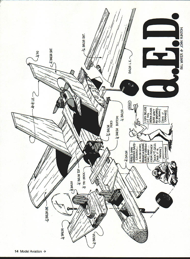
Q.E.D.
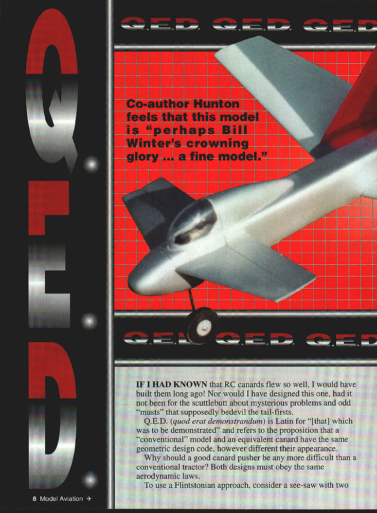
If I had known that RC canards flew so well, I would have built them long ago. Nor would I have designed this one, had it not been for the scuttlebutt about mysterious problems and odd "musts" that supposedly bedevil tail-firsts.
Q.E.D. (quod erat demonstrandum) is Latin for "[that] which was to be demonstrated" and refers to the proposition that a "conventional" model and an equivalent canard have the same geometric design code, however different their appearance.
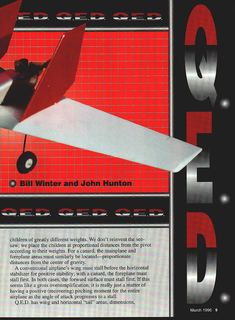
Why should a good canard pusher be any more difficult than a conventional tractor? Both designs must obey the same aerodynamic laws. To use a Flintstonian approach, consider a see-saw with two children of greatly different weights. We don't reinvent the see-saw; we place the children at proportional distances from the pivot according to their weights. For a canard, the mainplane and foreplane areas must similarly be located—proportionate distances from the center of gravity.
A conventional airplane's wing must stall before the horizontal stabilizer for positive stability; with a canard, the foreplane must stall first. In both cases, the forward surface must stall first. This is really just a matter of having a positive (recovering) pitching moment for the entire airplane as the angle of attack progresses to a stall.
Q.E.D. has wing and horizontal "tail" areas, dimensions, airfoils, and decalage identical to a fine-flying cabin design. The Q.E.D. configuration evolves from the truism that form follows function. Cosmetics were not an objective; the planform was generated by standard engineering procedures to arrive at a natural balance without ballast. A 1/3-scale sheet-balsa glider was built with the proper design CG location and checked by hanging the glider with thread and a straight pin. Ballasted to the design CG before flight, it proved a fine flier.
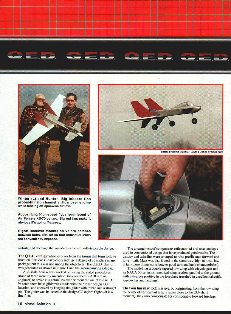
The arrangement of components reflects tried-and-true concepts used in conventional design that have produced good results. The canopy and twin fins were arranged to raise profile area forward and lower it aft. Mass was distributed in the same way: high at the nose, low at the tail—contributing to good turn-and-bank characteristics.
The model has a double-tapered low wing, tricycle gear, and a NACA 00-series symmetrical wing section. With the wing parallel to the ground and the foreplane set 3° positive, takeoffs, approaches and landings are excellent.
The twin fins may look massive, but originating from the low wing the center of vertical tail area is rather close to the CG (short moment); they also compensate for considerable forward fuselage area. Large inboard fins help channel airflow over the engine and fence off spanwise flow. A large 12-inch canopy contributes to turning excellence. Tests with the hand-launched glider confirmed the vertical area could be reduced only to a point without loss of stability. Fencing and a fenced propeller are preferred over tip fins; placing surfaces closer to the centerline makes them less subject to damage. A steerable nosewheel is fitted; downthrust is 3°.
An identical-cabin model used a balsa-skinned foam wing for good airfoil accuracy, strength, and easy building; the remainder of the model is conventional built-up balsa. Making the model balance at the design CG was an anticipated problem because of the weight of the pusher engine and fuel tank. A modest wing sweep was used—approximately 15° leading edge, 3° trailing edge. A center-wing cutout for the prop was rejected as too complex. A battery pack in the nose and a group of four servos immediately behind the foreplane proved the balance system perfectly.
At this juncture Sig Manufacturing introduced the Tri-Star canard. Struck by similarities in methodology, I compared notes with designer Ray Satterlee, who obtained an advance kit; its ingenious design flies very well. Ray's experience confirmed the approach and provided further encouragement in building the Q.E.D. prototype.
Figure 1 illustrates the sequence of steps used to develop Q.E.D. The drawing is also arranged to enable building a quick 1/3-scale sheet-balsa test glider. The test glider should be thrown hard like normal hand-launched gliders; it must not be released gently dead ahead. Velocity must be gauged to duplicate its natural glide angle.
Layout Development for Q.E.D.
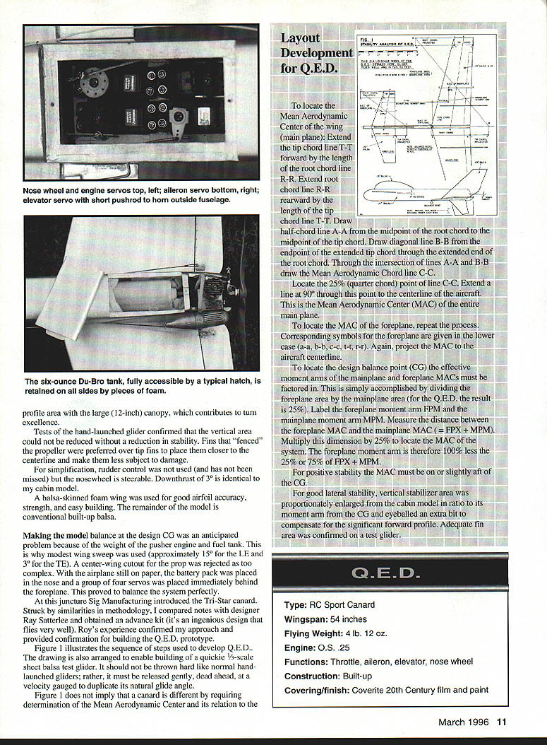
To locate the Mean Aerodynamic Center (MAC) of the wing (main plane):
- Extend the tip chord line T–T forward by the length of the root chord line R–R.
- Extend root chord line R–R rearward by the length of the tip chord line T–T.
- Draw the half-chord line A–A from the midpoint of the root chord to the midpoint of the tip chord.
- Draw diagonal line B–B from the endpoint of the extended tip chord through the extended end of the root chord.
- Through the intersection of lines A–A and B–B draw the Mean Aerodynamic Chord line C–C.
- Locate the 25% (quarter-chord) point of line C–C. Extend a line at 90° through this point to the aircraft centerline. This intersection is the MAC of the entire mainplane.
To locate the MAC of the foreplane, repeat the process using the corresponding lower-case symbols (a–a, b–b, c–c, t–t, r–r). Project the foreplane MAC to the aircraft centerline.
To locate the design balance point (CG) the effective moment arms of the mainplane and foreplane MACs must be factored in:
- Divide the foreplane area by the mainplane area (for Q.E.D. the result is 25%).
- Label the foreplane moment arm FPM and the mainplane moment arm MPM.
- Measure the distance between the foreplane MAC and the mainplane MAC = FPM + MPM.
- Multiply this dimension by the foreplane-area ratio (25% for Q.E.D.) to locate the MAC of the two-surface system.
- The foreplane moment arm is therefore 100% − 25% = 75% of (FPM + MPM).
For positive stability the combined MAC must be on or slightly aft of the CG.
For good lateral stability, vertical stabilizer area was proportionately enlarged from the cabin model in ratio to its moment arm from the CG and eyeballed a bit extra to compensate for the significant forward profile. Adequate fin area was confirmed on a test glider.
Q.E.D. Specifications
- Type: RC Sport Canard
- Wingspan: 54 inches
- Flying weight: 4 lb 12 oz
- Engine: O.S. .25
- Functions: Throttle, aileron, elevator, nose wheel
- Construction: Built-up
- Covering/finish: Coverite 21st Century film and paint
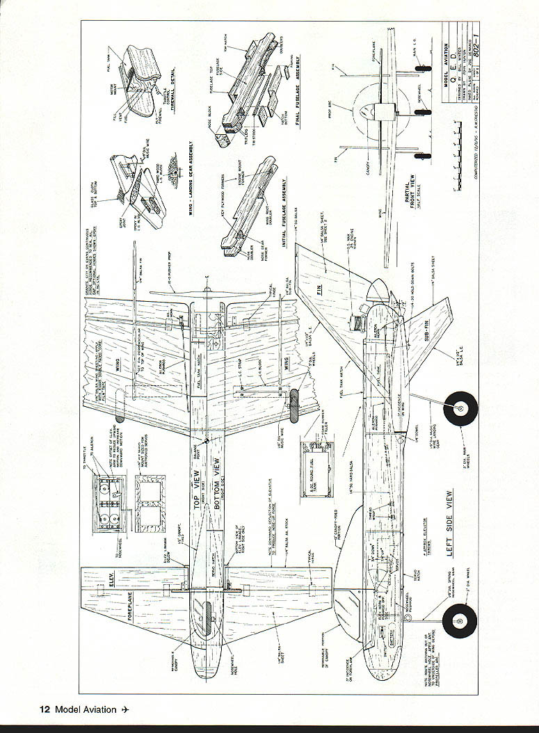
FIG. 1 — Plan, Elevation and Assembly Details
Views and assembly illustrations included:
- Top view
- Bottom view
- Left side view
- Partial front view
- Initial fuselage assembly
- Final fuselage assembly
- Firewall detail
- Wing landing gear assembly / nose wheel
- Former / wing root detail
- Nose wheel / wing landing gear assembly
- Typical hatch
- Servo locations and other component locations
Servo locations (as shown on the plans):
- Nose-wheel servo / engine servos — top left
- Aileron servo — top left
- Elevator servo — bottom right
- Short pushrod horn outside fuselage
Tank:
- Six-ounce Du-Bro tank — fully accessible
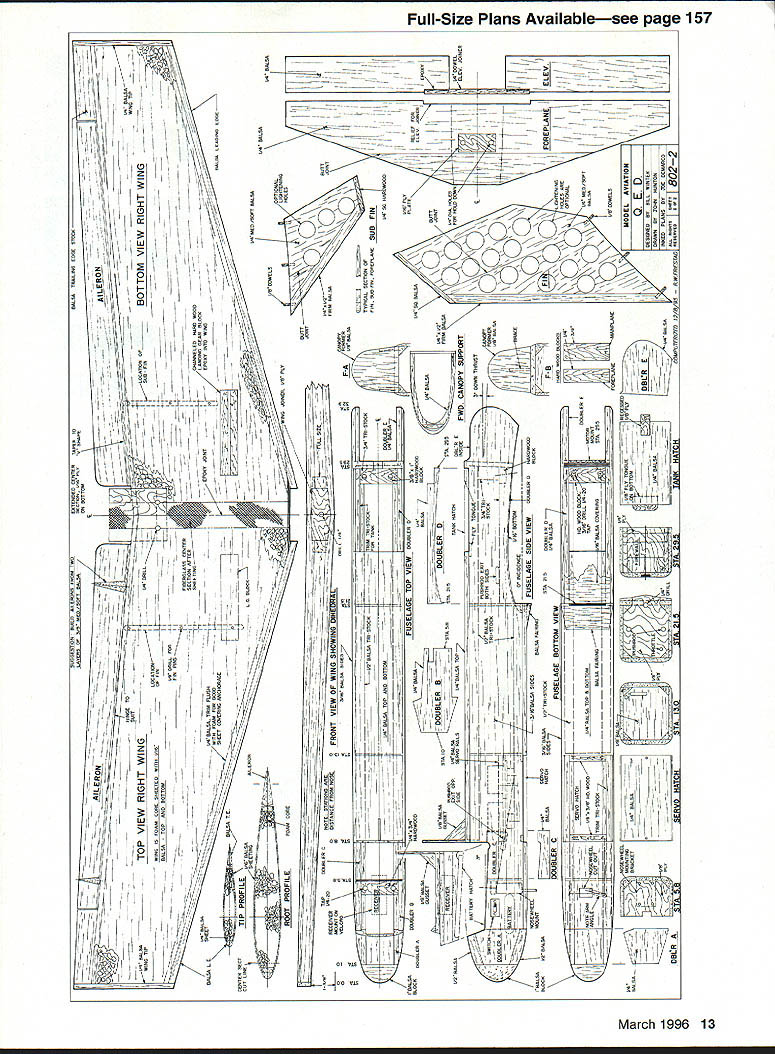
Miscellaneous notes shown on the drawings:
- Canopy
- Twin fins
- Foreplane
- Locking bolts / screws (fasteners shown on assemblies)
- Control horns and linkage details shown on drawings
- Scale and station lines shown on plan
(Labelled dimensions, rib spacing, sheet-balsa parts, and other small detail callouts are shown on the drawing.) Full-size plans available—see page 157.
CONSTRUCTION
Proper selection of wood provides easier construction and considerable weight savings. Order selected light balsa from supply houses and be sure to order more wood than you actually need so you can pick the best pieces. Wood thicknesses are noted on the plans.
Use cyanoacrylate (CYA) glue for general assembly and Titebond where slow-drying glue is needed.
Fuselage
- The fuselage is basic box construction from front to rear. Pin the sides together while cutting foreplane and wing slots so the stubs will be identical.
- Lay out the positions of all formers on the sides. Install the triangular strips on the sides; these triangles run straight from the firewall to the nose. Cut out all formers, tailoring them to the actual size of the triangles.
- Cut out the firewall and nosewheel mount, drill them to suit, and install blind nuts.
- Install the firewall and nosewheel mount to one fuselage side, using a small triangle to align the parts. Attach the other side. Install all formers, doublers, servo tray rails, and hardwood hold-down blocks.
- Block-sand the fuselage top and bottom flat. Install the servo tray with servos, route wires to the battery compartment, then add all linkages.
- Cut out all hatches and install the remaining top and bottom sheet parts. Trim the triangles in the hatch areas. Install the remaining nose parts, including a tacked-in foreplane blank (3 inches wide). Tack-glue the hatches back in.
- Rough-shape the fuselage, then sand to final shape. Install canopy formers and supports.
- The wing mount bottom sheeting is placed cross-grained.
- Assemble the fuel tank with flexible silicon tubing looped back so that the pickup is in the rear of the tank (nearest the engine). Trial-fit the tank with tubes, remove it and seal all surfaces in the tank compartment and engine areas with epoxy. Install the tank and engine. Trial-fit the nosewheel strut, set the nosewheel arm at the proper angle, remove the strut, and file a flat where the screw bears.
- Do not drill and tap for mainplane or foreplane hold-downs until final fitting.
Wing
- Have the wing cores cut to the required airfoil shape. Keep the parts the cores come in and lay the wing into these parts on a flat surface.
- Vacuum the cores thoroughly. Install the leading edge doubler, trailing edge spar, and landing gear blocks with Titebond.
- Use Evans core-film double-faced tape or 3M spray adhesive to adhere the balsa covering (test any proposed substitutes, which may melt the foam). Butt-glue balsa sheets together before applying them. The balsa covering extends over the leading edge doubler and the aileron spar for good adhesion—glue with Titebond here. Use foam-friendly CA through pinholes to fix any sheathed areas that do not stick down completely. Press skins down firmly while inserting glue.
- Sand leading and trailing edges and wingtips of the sheathed panel flat with a long sanding block and install the balsa LE, TE, and wingtips with Titebond. Rough-shape these parts, then sand the wing halves to shape with fine sandpaper on a long block.
- Match the width and basic airfoil shape at the root of the panels. Prop the wingtips up with a balsa block pinned into place. Use the flat sanding block along a table edge to trim the wing roots to the proper dihedral angle. Check the fit to ensure no large gaps top or bottom when panels are fitted.
- To join panels, anchor one panel flat on the bench over waxed paper, block up the other panel to the specified dimension, and join the wing roots with epoxy. Install the front plywood dowel support. Add the trailing edge root parts.
- Wrap the wing center section with 1/2-inch-wide (minimum) medium-weight fiberglass (see Figure 1).
Note: use CA to wick down coverings where needed.
Fins and Foreplane
- Cut parts from sheet and butt-join as required. Keep fins light with proper balsa selection and optional lightening holes.
- Sand surfaces smooth, taper trailing edges of fins and elevator, and round leading edges. Join the elevators with a 1/8-inch dowel positioned on its center of rotation to keep the fuselage clearance hole small. Use a straightedge to check elevator alignment.
- The ailerons can be fabricated from two layers of light material and sanded to a tapered shape. If using iron-on I-type hinges, apply them before covering.
Covering
- Coverite 21st Century film and spray paint were used for the original finish. Film was used on the wing and fins and paint on the fuselage and foreplane, but you may cover the entire model with film if desired.
- Follow the film manufacturer's directions. If possible, use an iron with a thermometer to set temperatures correctly. If not available, set the iron to just melt the adhesive for initial positioning, then raise it for sealing and shrinking.
- Cover the top with a light color and the bottom dark for good recognition when flying.
Final Assembly
- Drill a "sloppy" hole in the wing for the leading-edge dowel, epoxy the dowel in place. Slip a piece of waxed paper over the dowel and slip the wing into place for curing.
- Check equal distance from each wingtip to the nose, then drill 3/16-inch holes for the hold-down screws. Re-drill the wing for dowel clearance, then tap the fuselage block for 4-40.
- Mount the foreplane similarly, checking for squareness. Install the landing gear, nosewheel, engine, fuel tank, control horns, and all linkages.
- Remove covering where the fins are to be installed. Use a balsa triangle (with the "toe" cut out to clear the glue joint) to align the fins while affixing them.
- Check control throws shown on the plans. Before flying, check the balance point carefully and add ballast if necessary.
- The forward-pointing exhaust may look incongruous, but no apparent performance reduction was noted. A 1/2-inch copper "L" can be added to deflect the exhaust upward if desired.
Fins and Foreplane Notes
- Keep fins light; drill optional lightening holes if needed.
- Fenced fins around the propeller are preferred over tip fins to keep surfaces close to the centerline and less subject to damage.
- Tests with hand-launched gliders confirmed appropriate vertical area for stability.
Flying Q.E.D.
These notes should allay reservations about building an "unorthodox" canard. The model is completely orthodox to fly except for appearance and some additional benefits the design brings.
- Engine/takeoff checks: Many modelers run the engine at full speed while holding the nose up to ensure it does not go lean during takeoff acceleration. Q.E.D.'s fuel tank is ahead of the engine; the engine tends to richen slightly during takeoff, so the needle valve can be set "right on" without sagging. The plans show how to loop the clunk and tube so the pickup is at the rear of the tank.
- Ground handling: This canard has no rudder control. Steering during takeoff is not a problem. There is no prop blast over the elevator, so there is no premature rotation and nose liftoff. The nosewheel stays in contact with the ground until the foreplane lifts.
- Climbout: Keep good airspeed to help pusher-engine cooling. There is no danger of overheating stall because the foreplane stalls before the main wing, making it difficult or impossible to stall the main wing.
- In-flight handling: Expect normal control responses in all phases. Q.E.D. has a snappy roll rate, inverts well, will loop, Immelmann, snap, do Cuban eights, and spin.
- Spinning: With no rudder control, a spin is induced at stall (power on or off) with up elevator and aileron to one side. With full up elevator the spin starts slowly, then the turn rate increases until the spin abruptly flattens out after about three turns as the stalled wing comes out of proper flow. You can maintain a spin by holding less up elevator or aileron after the spin starts. When experimenting with spins, fly well away from the ground until you are used to the model's behavior.
- Orientation: The canard looks different in the air than a tractor model, particularly wing-edge-on. Fly at altitude until you are comfortable so you can make quick decisions when it is low.
- Efficiency: As you level off for cruise the lift-to-drag ratio becomes high; the model is more efficient than a comparable conventional model and can be soared at low power.
- Power changes: There is very little pitch change if power is adjusted slowly and smoothly (downthrust reduces pitch coupling). If power is reduced suddenly the foreplane may rise slightly. There are few torque effects and no surfaces in the propeller slipstream, producing excellent tracking.
- Landing: The most pleasant surprise is landing—Q.E.D. is remarkably easy. You can add power and go around at any time with no pitch or torque changes. It is possible to get Q.E.D. flying too slowly because of its benign stall traits; keep some speed for proper flare. It has a tendency to float (but not balloon) in ground effect, so fly down with slight forward stick and let speed bleed off; you can achieve very smooth landings.
Q.E.D. is an exceptional model to fly. While easy to fly, it is relatively small and aerobatic. It is not intended for beginners, but a moderately experienced pilot will have a great time with it. The Q.E.D. is distinctive and unusual looking, but it flies as reliably as any conventional model.
Enjoy!
Bill Winter 12811 Melville Ln. Fairfax, VA 22033
John Hunton 3722 Spicewood Dr. Annandale, VA 22003
Transcribed from original scans by AI. Minor OCR errors may remain.

