
QUANTUM 20
Len Surtees
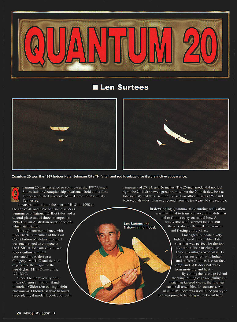
Quantum 20 was designed to compete at the 1997 United States Indoor Championships/Nationals held at the East Tennessee State University Mini-Dome, Johnson City, Tennessee.
In Australia I took up the sport of HLG in 1990 at the age of 40 and have had some success, winning two National OHLG titles and a second place out of three attempts. In 1994 I set an Australian outdoor record, which still stands.
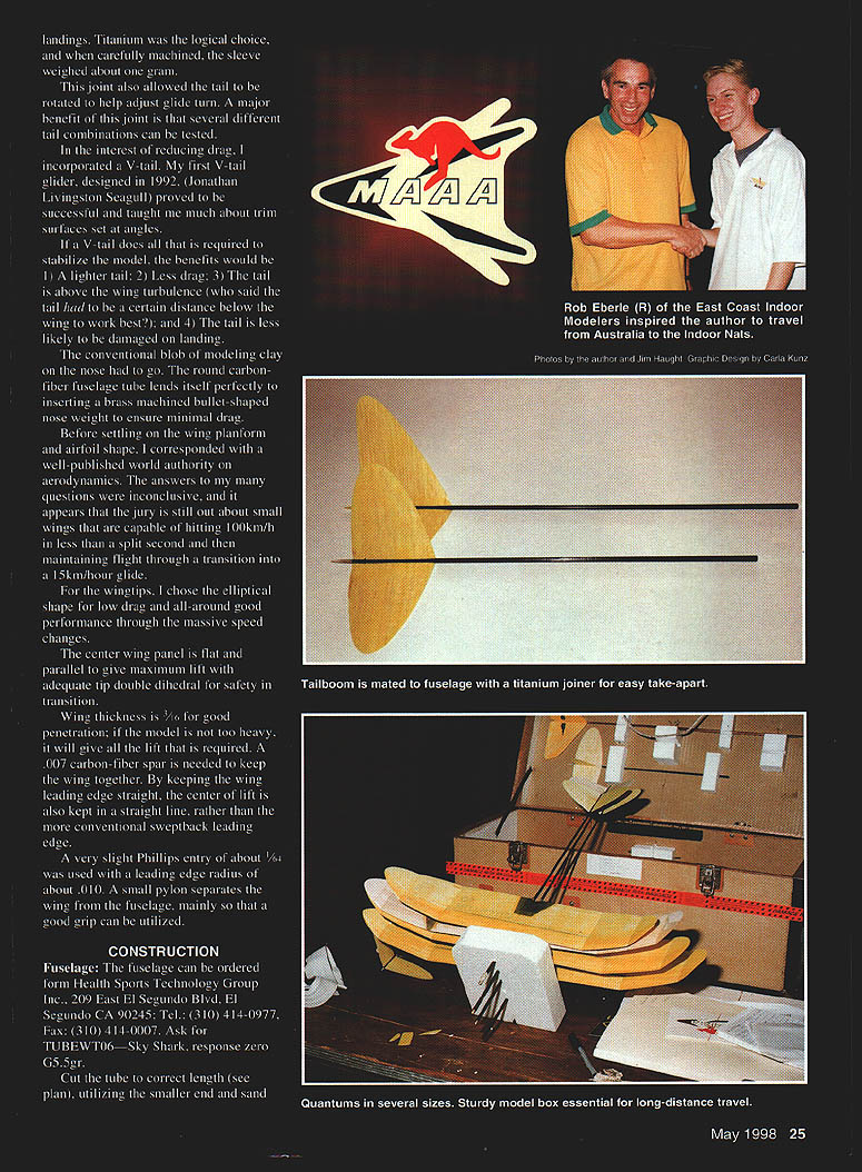
Through correspondence with Rob Eberle (a member of the East Coast Indoor Modelers group), I was encouraged to compete at the USIC at Johnson City. It was Rob's enthusiasm that motivated me to design a Category IV HLG and to experience the magic of the world-class Mini-Dome at the '97 USIC.
Since I had previously only flown Category I Indoor Hand-Launched Glider (8 m ceiling height maximum), I thought it wise to build three identical model layouts, with wingspans of 20, 24, and 26 inches. The 26-inch model did not feel right; the 24-inch showed great promise; but the 20-inch flew best at Johnson City and was used for my last two official flights (75.2 and 76.6 seconds — less than one second from the ten-year-old site record).
In developing Quantum, a major constraint was transporting several models in a carry-on model box. A removable wing seemed logical, but joints can introduce movement and flexing. I located a very light, tapered carbon-fiber kite spar that was perfect for the job. A carbon-fiber fuselage has three advantages over balsa:
- For a given length it is lighter and stiffer.
- It has less surface drag.
- It does not warp from moisture and heat.
By cutting the fuselage behind the wing trailing edge and gluing in a matching tapered sleeve, the fuselage can be disassembled for transport. An aluminum sleeve was used in the prototype but was prone to bending on hard landings. I then made a titanium sleeve about 1-1/4 inches long, approximately 0.010" wall thickness, which weighed just under 1 gram. Machine the sleeve so that half its length is parallel (this half is epoxied into the rear half of the fuselage) and the other half has approximately 0.003" taper over 5/8 inch. The carefully machined rear half of the fuselage will wriggle up the sleeve and seat snugly.
Scuff the inside of the fuselage with a small rat-tail file to give the epoxy a good key; ensure the sleeve is clean. Smear a small amount of 15-minute epoxy inside the forward fuselage, press the sleeve firmly into the rear fuselage, then carefully rotate the sleeve into the forward fuselage. Wipe off excess glue and leave about a 1/32" gap at the joint. Lay the assembly on wax paper on a flat surface against a straightedge for side alignment and leave to set. Done properly, perfect straight alignment can be achieved.
Carbon fiber does not like hard impacts; to lessen the likelihood of splitting, wrap tissue around the nose and the fuselage end that slips over the sleeve, and finish with shrinking dope. Glue a four‑pound balsa fairing about 1/2" long to streamline the end of the fuselage rather than leave a 1/8" square end. This joint also allows the tail to be rotated to help adjust glide turn; a major benefit is that several different tail combinations can be tested.
In the interest of reducing drag I incorporated a V-tail. My first V-tail glider (1992, Jonathan Livingston Seagull) taught me much about trim surfaces set at angles. If a V-tail provides the required stability, the benefits are:
- A lighter tail.
- Less drag.
- The tail sits above the wing turbulence.
- The tail is less likely to be damaged on landing.
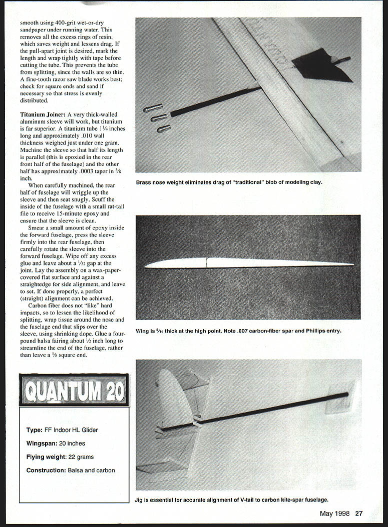
The conventional blob of modelling clay on the nose had to go. The round carbon-fiber fuselage tube lends itself perfectly to inserting a machined brass bullet-shaped nose weight to ensure minimal drag.
Before settling on the wing planform and airfoil, I corresponded with a well-published world authority on aerodynamics. The answers were inconclusive; the jury is still out about very small wings that can hit 100 km/h almost instantly and then maintain flight through a transition into a 15 km/h glide.
For the wingtips I chose an elliptical shape for low drag and all-around good performance through massive speed changes. The center wing panel is flat and parallel to give maximum lift with adequate tip double dihedral for safety in transition. Wing thickness is 1/16" for good penetration; if the model is not too heavy, it will give all the lift required. A 0.007" carbon-fiber spar is needed to keep the wing together. By keeping the wing leading edge straight, the center of lift is kept in a straight line rather than with a sweptback leading edge.
A very slight Phillips entry of about 1/64" was used with a leading edge radius of about 0.010". A small pylon separates the wing from the fuselage, mainly so that a good grip can be utilized.
CONSTRUCTION
Fuselage
The fuselage tube can be ordered from Health Sports Technology Group Inc., 209 East El Segundo Blvd., El Segundo, CA 90245; Tel.: (310) 414-0977; Fax: (310) 414-0007. Ask for TUBEWT06 — Sky Shark, response zero G5.5R.
Cut the tube to the correct length (see plan), utilizing the smaller end and sand smooth. Using 400-grit wet-or-dry sandpaper under running water removes excess resin, saves weight and lessens drag. For a pull-apart joint, mark the desired length and wrap tightly with tape before cutting the tube to prevent splitting (the walls are thin); a fine-tooth razor saw blade works best. Check for square ends and sand as necessary so stress is evenly distributed. A very thick-walled aluminum sleeve will work, but titanium is far superior.
A titanium tube 1-1/4 inches long and approximately 0.010" wall thickness weighed just under one gram. Machine the sleeve so that half its length is parallel (this is epoxied in the rear half of the fuselage) and the other half has approximately 0.003" taper in 5/8 inch. When carefully machined, the rear half of the fuselage will wriggle up the sleeve and seat snugly.
Scuff the inside of the fuselage with a small rat-tail file to receive 15-minute epoxy and ensure that the sleeve is clean. Smear a small amount of epoxy inside the forward fuselage, press the sleeve firmly into the rear fuselage, then carefully rotate the sleeve into the forward fuselage. Wipe off any excess glue and leave about a 1/32" gap at the joint. Lay the assembly on wax paper on a flat surface and against a straightedge for side alignment, and leave to set. If done properly, perfect straight alignment can be achieved.
Carbon fiber does not like hard impacts, so to lessen the likelihood of splitting, wrap tissue around the nose and the fuselage end that slips over the sleeve, using shrinking dope. Glue a four-pound balsa fairing about 1/2" long to streamline the end of the fuselage, rather than leave a 1/8" square end.
Type: FF Indoor HL Glider Wingspan: 20 inches Flying weight: 22 grams Construction: Balsa and carbon
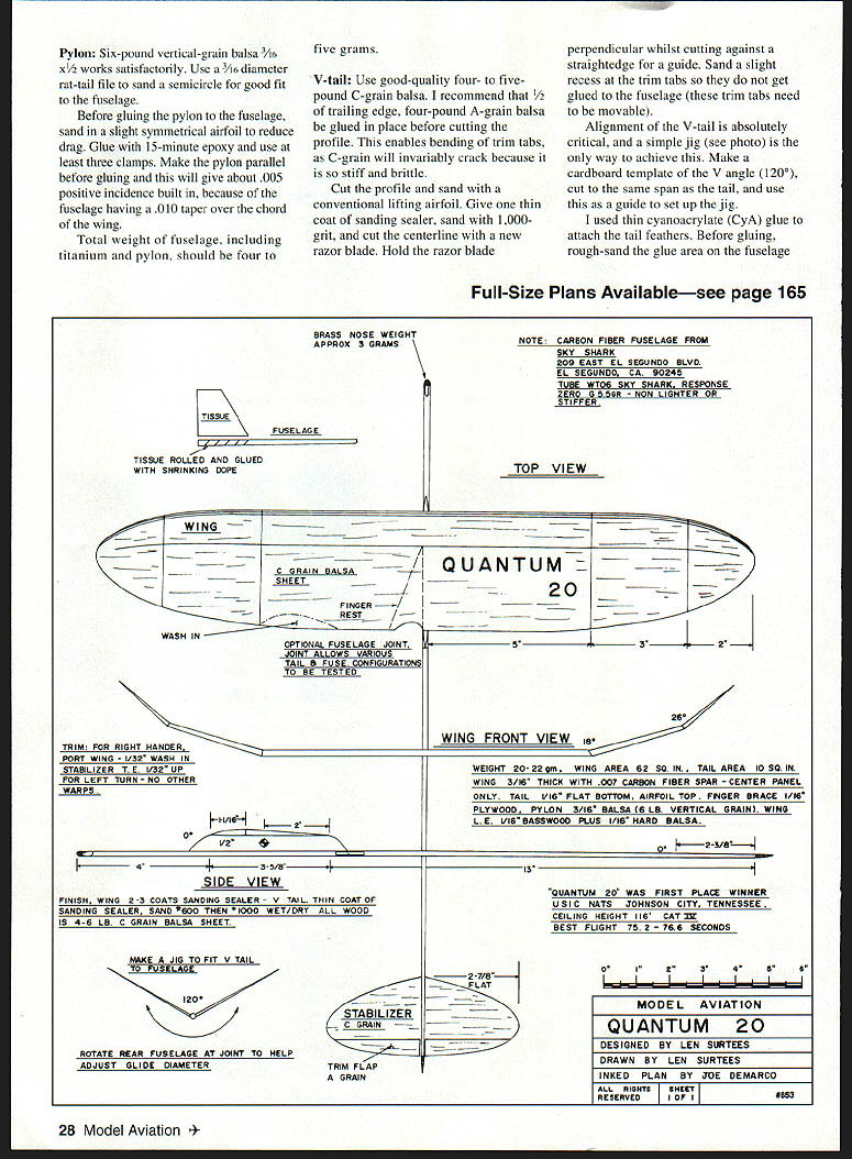
BRASS NOSE WEIGHT — approx. 3 grams
TISSUE FUSELAGE — Tissue rolled and glued with shrinking dope. Wash-in optional fuselage joint. Joint allows various tail & fuse configurations to be tested.
(Note: carbon-fiber fuselage from Sky Shark / Health Sports Technology Group Inc.)
Pylon
Six-pound vertical-grain balsa 3/16 x 3/8 works satisfactorily. Use a 3/16" diameter rat-tail file to sand a semicircle for a good fit to the fuselage. Before gluing the pylon to the fuselage, sand in a slight symmetrical airfoil to reduce drag. Glue with 15-minute epoxy and use at least three clamps. Make the pylon parallel before gluing — this will give about 0.005" positive incidence built in, because the fuselage has a 0.010" taper over the chord of the wing.
Total weight of fuselage, including titanium sleeve and pylon, should be four to five grams.
V-tail
Use good-quality four- to five-pound C-grain balsa. I recommend gluing a 1/32" trailing-edge strip of four-pound A-grain balsa in place before cutting the profile. This enables bending of trim tabs, as C-grain will invariably crack because it is so stiff and brittle.
Cut the profile and sand with a conventional lifting airfoil. Give one thin coat of sanding sealer, sand with 1,000 grit, and cut the centerline with a new razor blade. Hold the razor blade perpendicular while cutting against a straightedge for a guide. Sand a slight recess at the trim tabs so they do not get glued to the fuselage (these trim tabs need to be movable).
Alignment of the V-tail is absolutely critical; a simple jig is the only way to achieve this. Make a cardboard template of the V angle (120°), cut to the same span as the tail, and use this as a guide to set up the jig.
I used thin cyanoacrylate (CyA) glue to attach the tail feathers. Before gluing, rough-sand the glue area on the fuselage.
Make a jig to fit the V-tail to the fuselage (120°). Rotate the rear fuselage at the joint to help stabilizer/trim-flap grain alignment.
Full-size plans available — see page 165.
Wing
For wingtips I used an elliptical shape for low drag and all-around good performance through speed changes. The center panel is flat and parallel to give maximum lift with adequate tip double dihedral for safety in transition. Wing thickness is 1/16" with a 0.007" carbon-fiber spar. Keep the wing leading edge straight so the center of lift remains in a straight line.
A very slight Phillips entry of about 1/64" was used with a leading edge radius of about 0.010". A small pylon separates the wing from the fuselage to allow a secure grip.
Glue the wing to the pylon (rough up the fuselage where the wing will attach) with Titebond or 15-minute epoxy. No wing offset is used. To help hold the wing to the pylon after the glue has set, mix some microballoons with 15-minute epoxy and use the tip of your finger to make a small fillet between the wing and pylon (do this after the finger rest is in place).
Finish
- Wing: 2–3 coats sanding sealer.
- V-tail: Thin coat of sanding sealer; sand 600 then wet/dry.
- All wood: 4–6 lb C‑grain balsa sheet.
Trimming
Locating the correct center of gravity (CG) for your throwing style is probably the most important aspect of trimming. The harder you throw, the farther the CG must be moved rearward to prevent looping in the climb; small shifts can have a large effect.
To determine the correct nose weight, use clay wrapped around the nose to establish proper glide trim. If this CG location also allows a good high launch and satisfactory transition, weigh the clay and machine a streamlined brass shape of equivalent weight. Make a couple of spares (about 1/2 gram heavier and lighter) for fine trimming. Small amounts of weight can be filed from the inner end. Make weights a firm push-in fit so they can be interchangeable.
Initial trim testing is done by pushing the glider from shoulder height with the nose slightly down at the estimated glide speed. Trim until a floating glide is evident, with a slight turn to the left (for right‑handed throwers).
- Bending the right stab trim tab up will induce left turn with the nose wanting to rise.
- Bending a little left stab trim tab down will also turn the model to the left but with the nose wanting to fall. Go easy — very small deflections (as little as 1/64") can have a large effect.
Take your time in evaluating which warp is needed to get the result you want.
Once satisfied with glide trim, proceed to launch trimming. Hold the model with the wing and fuselage parallel to the ground, throw firmly in the horizontal position, and trim for the following sequence:
If the CG is correct, Quantum should fly straight and true for about 50–75 feet; then, as speed washes off, the nose should slowly start to rise into a large left circle. The model should complete two circles and land back at your feet. At this point you are ready for a hard launch.
Bank Quantum 20 at about 30° and launch at a 60° angle of attack. Quantum 20 has no spiral‑up tendencies; it holds its angle of bank in an elliptical curve to the transition point, arriving approximately right‑wing‑down in a vertical position. Because of the severe wingtip dihedral, Quantum then simply flops down into its glide mode, facing approximately 180° from launch position.
Grip technique is critical. Hold the model tightly at the beginning of the runup and continue squeezing until you are practically crushing the model at the point of release, with your index finger loaded like a tightly wound spring. If you cannot grip the model tightly and unleash that dynamic power, you will have difficulty competing in the real world of Indoor Category IV Hand-Launch Glider.
Quantum 20 was the PLA winner.
Len Surtees 10 Woodview Cres Tamworth NSW 2340 Australia
MODEL AVIATION Quantum — Designed by Len Surtees Drawn by Len Surtees Inked plan by Joe DeMarco All rights reserved
Transcribed from original scans by AI. Minor OCR errors may remain.

