

Que d'Coupe
BABY WAKEFIELD! You never hear the term anymore, but this "in a nutshell" phrase did more to attract me to Coupe d'Hiver than any other factor. Maybe you have given a longing look at Wakefield, but have stopped short after noticing the seeming complexity of the typical competition model.
The Coupe event offers the perfect introduction to rubber competition and ultimately to Wakefield. Experience gained handling the Coupe is directly applicable to the larger models. Construction methods, trimming techniques, pre-flight procedures, air picking and launch are all basically similar.
Coupe is not a high-performance event. Ten grams of rubber in a 70-gram airframe requires good air to produce the 2-minute max. Similarly, a 40-gram motor and 190-gram airframe Wakefield, although a somewhat more favorable power loading, needs good air to make 180 seconds.
Coupe popularity suffered from a change to 100 grams total weight a few years ago. Some avid competitors built new models for the new rules, particularly in Europe, and did quite well, but here in the U.S. many modelers simply ballasted their old models to 100 grams with only mediocre success.
Coupe entries in local contests diminished to an all time low and many feared the event would die. Forces rallied to the cause, however, and about two years ago the rules were changed back to 80 grams all-up weight. Contest entries during the past year or so have proved the wisdom of the change.
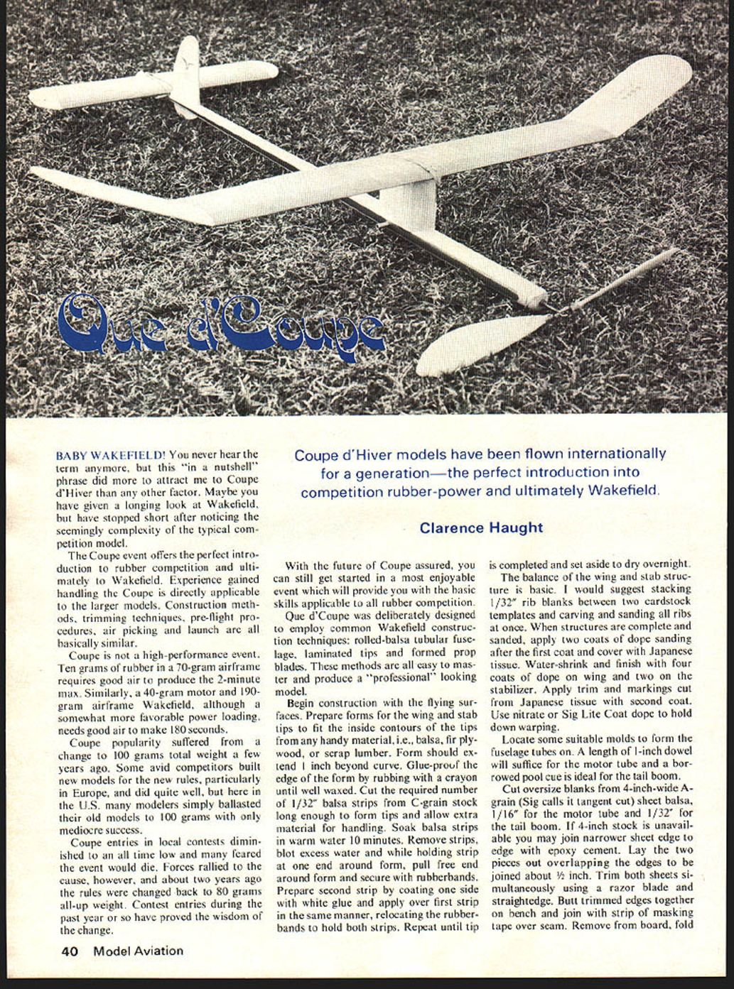
Coupe d'Hiver models have been flown internationally for a generation—the perfect introduction into competition rubber-power and ultimately Wakefield.
Clarence Haught
With the future of Coupe assured, you can still get started in a most enjoyable event which will provide you with the basic skills applicable to all rubber competition.
Que d'Coupe was deliberately designed to employ common Wakefield construction techniques: rolled-balsa tubular fuselage, laminated tips and formed prop blades. These methods are all easy to master and produce a "professional" looking model.
Begin construction with the flying surfaces. Prepare forms for the wing and stab tips to fit the inside contours of the tips from any handy material, i.e., balsa, fir plywood, or scrap lumber. Form should extend 1/8 inch beyond curve. Glue-proof the edge of the form by rubbing with a crayon until well waxed. Cut the required number of 1/32" balsa strips from C-grain stock long enough to form tips and allow extra material for handling. Soak balsa strips in warm water 10 minutes. Remove strips, blot excess water and while holding strip at one end around form, pull free end around form and secure with rubberbands. Prepare second strip by coating one side with white glue and apply over first strip in the same manner, relocating the rubberbands to hold both strips. Repeat until tip is completed and set aside to dry overnight.
The balance of the wing and stab structure is basic. I would suggest stacking 1/32" rib blanks between two cardstock templates and carving and sanding all ribs at once. When structures are complete and sanded, apply two coats of dope sanding after the first coat and cover with Japanese tissue. Water-shrink and finish with four coats of dope on wing and two on the stabilizer. Apply trim and markings cut from Japanese tissue with second coat. Use nitrate or Sig Lite Coat dope to hold down warping.
Locate some suitable molds to form the fuselage tubes. A length of 1-inch dowel will suffice for the motor tube and a borrowed pool cue is ideal for the tail boom. Cut oversize blanks from 4-inch-wide A-grain (Sig calls it tangent cut) sheet balsa, 1/16" for the motor tube and 1/32" for the tail boom. If 4-inch stock is unavailable you may join narrower sheet edge to edge with epoxy cement. Lay the two pieces out overlapping the edges to be joined about 1/2 inch. Trim both sheets simultaneously using a razor blade and straightedge. Butt trimmed edges together on the bench and join with a strip of masking tape over the seam. Remove from board, fold around form and secure with rubberbands.
Soak fuselage blanks in water 10 minutes. Remove, wrap around forms allowing excess sheet to overlap beveled edge. Bind with cloth bandage and allow to dry overnight. At the same time prepare 1/32" plywood reinforcements. Wrap soaked plywood around the same mold and allow to dry. Remove blanks from forms and cement seams supporting the tubular sections on a 1/2-inch dowel while gluing. Do not glue up fuselage tubes on forming molds as you will have difficulty removing the finished tube. When dry, trim off excess sheet and sand smooth.
Fit plywood nose reinforcement and install. Make up motor peg reinforcement and fuselage joiner and install at rear of motor tube. Drill 3/16-inch holes for motor peg. These are best drilled with a sharpened piece of 1/8-inch brass tubing in an electric drill. Support motor tube on a short length of dowel while drilling. Install a 1/8-inch balsa bulkhead in the end of the fuselage joiner. Fit rear boom and cement in place.
Sight down completed fuselage tube to determine straightness. If fuselage is not perfect, rotate until offset is on top and mark fuselage at top center for reference. Install rudder, stab rest, and D.T. hardware at rear end. Using a protractor for reference, sand in specified thrust angles at nose.
Plug motor peg holes and pour about 2 ounces of thinned dope into motor tube. Cap end and shake. Pour excess dope out and allow to dry. Repeat this operation at least one more time to seal interior of motor tube against rubber lube.
Dope outside of fuselage two coats, sanding between each. Cover tail boom with Japanese tissue and motor tube with two layers of silk or one layer of Silron as a protection against blown motors.
'Que d' Coupe'
Clarence Haught
Que d'Coupe
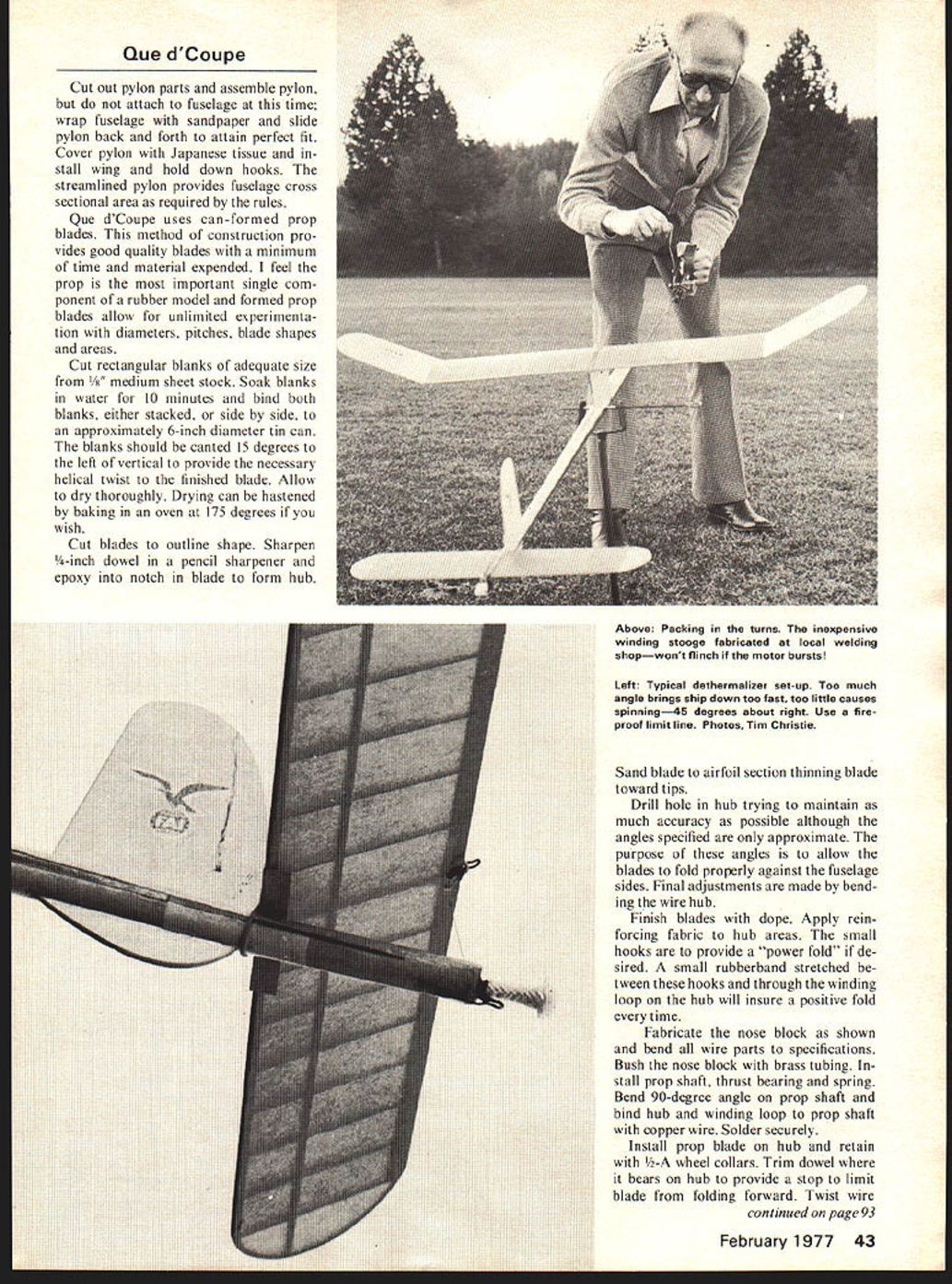
Cut out pylon parts and assemble pylon, but do not attach to fuselage at this time; wrap fuselage with sandpaper and slide pylon back and forth to attain perfect fit. Cover pylon with Japanese tissue and install wing and hold down hooks. The streamlined pylon provides fuselage cross sectional area as required by the rules.
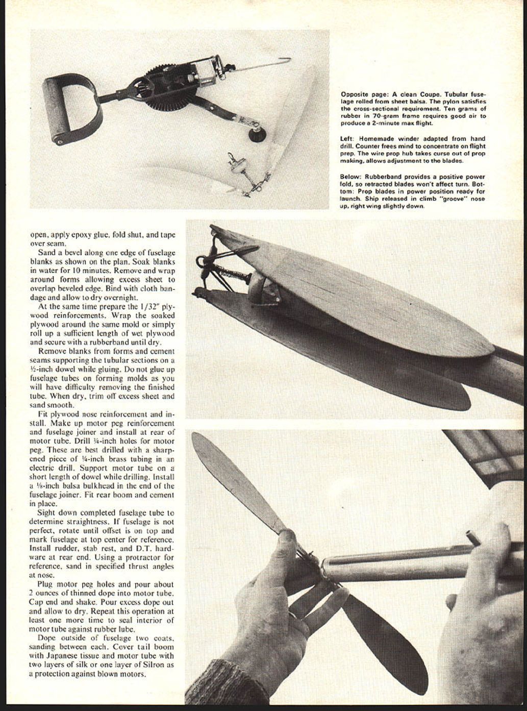
Que d'Coupe uses can-formed prop blades. This method of construction provides good quality blades with a minimum of time and material expended. I feel the prop is the most important single component of a rubber model and formed prop blades allow for unlimited experimentation with diameters, pitches, blade shapes and areas.
Cut rectangular blanks of adequate size from 1/8" medium sheet stock. Soak blanks in water for 10 minutes and bind both blanks, either stacked, or side by side, to an approximately 6-inch diameter tin can. The blanks should be canted 15 degrees to the left of vertical to provide the necessary helical twist to the finished blade. Allow to dry thoroughly. Drying can be hastened by baking in an oven at 175 degrees if you wish.
Cut blades to outline shape. Sharpen 1/4-inch dowel in a pencil sharpener and epoxy into notch in blade to form hub.
Sand blade to airfoil section, thinning blade toward tips.
Drill hole in hub trying to maintain as much accuracy as possible although the angles specified are only approximate. The purpose of these angles is to allow the blades to fold properly against the fuselage sides. Final adjustments are made by bending the wire hub.
Finish blades with dope. Apply reinforcing fabric to hub areas. The small hooks are to provide a "power fold" if desired. A small rubberband stretched between these hooks and through the winding loop on the hub will insure a positive fold every time.
Fabricate the nose block as shown and bend all wire parts to specifications. Bush the nose block with brass tubing. Install prop shaft, thrust bearing and spring. Bend 90-degree angle on prop shaft and bind hub and winding loop to prop shaft with copper wire. Solder securely.
Install prop blade on hub and retain with 1/2-A wheel collars. Trim dowel where it bears on hub to provide a stop to limit blade from folding forward. Twist wire
Que d'Coupe/Haught
hub to provide proper angle of 54 degrees to prop shaft at the 5-inch blade station.
Check prop for balance and add weight or sand heavy blade to bring prop into balance. Determine the proper location for the prop stop screw to stop prop in a horizontal position when tension is off shaft spring.
The winding hook shown on the plans is a desirable accessory as it allows the motor to be wound without the prop assembly. In practice the prop assembly is removed and the winder engaged directly to the winding hook. After winding, a length of music wire is inserted in the tubing on the winding hook to hold the wound motor while the prop and nose block assembly is hooked on.
This procedure lessens the possibility of damage from bursting motors during winding. Always secure the nose block with a retaining band as the jolt of a stopping prop can dislodge the nose block, disrupting flight trim.
The major dilemma facing rubber fliers today is the difficulty of obtaining quality rubber. Pirelli, the long time standard, is no longer available, and its replacement Filati does not measure up to old Pirelli standards, and is more inconsistent from batch to batch than old stocks. I understand Filati is getting better, but samples I have tested proved disappointing. Some old stock Pirelli is available if you want to pay the price, but quantities are limited and for this reason I recommend the use of something more available, in order that you may become thoroughly familiar with its characteristics, and your model will not need extensive retrimming with each new batch of rubber.
This leaves about two choices, Sig and FAI rubber sold by Ed Dolby of FAI Model Supply. I chose Dolby rubber. It takes fewer winds than Pirelli, and has a stronger initial burst, but good performance can be obtained from it. It is available 3/16" and 1/4" widths, and is reasonably priced.
I suggest you start with 1/4" FAI rubber and experiment with other sizes and brands when you and your model are fully acquainted.
Prepare several motors by cutting in lengths that weigh slightly under 10 grams. Wash thoroughly to remove talc and lubricate with a 50-50 mixture of glycerine and surgical jelly. Just pour a dab of lube in the palm of one hand and a motor in the other, and rub vigorously to thoroughly coat the motor.
Tie the ends together with an overhand knot pulled tight, and followed with a square knot snugged up. Clip off short ends.
Break in motors by stretching five times their length for 1 minute, then increasing stretch to six times length for another minute, and finally releasing tension gradually during a one-minute period. You can break in four or five motors at a time. A smooth door knob makes a good anchor for one end and a short length of 1/2-inch or larger dowel works good for the handle end.
Loop a motor into six strands and anchor one end solidly. Hook your winder to the other end. Stretch motor out approximately 30 inches, crank in about 175 turns and then move in slowly while continuing to wind and count. Wind until motor bursts and note number of turns. Use this figure as a guide when winding for flight. Allow a 5 percent safety margin.
A word about winders. If you are just planning on flying Coupe, a small shop "egg beater" type hand drill will do just fine.
Obtain a sturdy hook of 1/8" material from the hardware store and have a nut
Que d'Coupe (continued)
brazed on the threaded end to prevent the hook from pulling out of the drill chuck. Most of these drills have approximately 4-to-1 gear ratios. Determine what yours is so you can convert winder handle turns to motor turns.
If you plan to graduate to Wakefield and/or Unlimited, buy a ready made winder or make one from a heavy-duty hand drill. Attach a D-type handle, remove the chuck and install a permanent winding hook.
Que d'Coupe flies right power, right glide. Prepare for flight by double checking all surfaces for alignment. Rudder should be 1/16" right. Wing tab should be down 1/16". Tips washed out 1/16". Stab should be tilted right side 3/4" high. CG and thrust line as shown on plans. With all slack out of the motor and the prop blades held in the folded position with a rubber-band test glide, shimming stab, until a smooth floating glide with slight right turn is obtained.
Put 100 hand turns in the motor and launch to right of wind, nose up slightly. Observe carefully. A right moderate climbing turn indicates all is well. You are only looking for dangerous traits at this time. As long as the model does not spiral dive to the right continue to add power using the winder. If ship spiral dives reduce right thrust and increase wing tab down adjustment.
As you increase power to full winds correct climb turn and angle with thrust adjustments. A small sanding block in your flight kit is handy for this. Keep the right wing up with tab.
Adjust glide turn with stab tilt and glide angle with slight CG shifts. You may fine tune the flight trim with small rudder tab and stabilizer incidence adjustments.
Change motors every other flight when practicing and every flight in competition.
Fly in all kinds of weather and experiment with rubber. Try 3/16" 8-strand motors, etc. Try to put your Coupe in a thermal for a max. There have been some good articles on thermals lately. Check some of the RC glider columns.
Get that rubber technique down pat, then start looking for a good Wakefield design!
Transcribed from original scans by AI. Minor OCR errors may remain.

