
Radio Control Aerobatics
Eric Henderson [eric.henderson@comcast.net]
Modifications to a hinge-marking tool
Most of the ARFs I build/assemble come with pin-hinged, plastic-stick, or even metal hinges. I like to swap out the supplied hinges and replace them with Mylar hinges.
RC Aerobatics (Pattern) airplanes use relatively small control throws, typically in the range of 10°–15°. Mylar hinges handle this movement easily and have no “play” when the control surface is at center. They also seem to reduce the “complaining” we often hear from digital servos when holding a control surface at neutral.
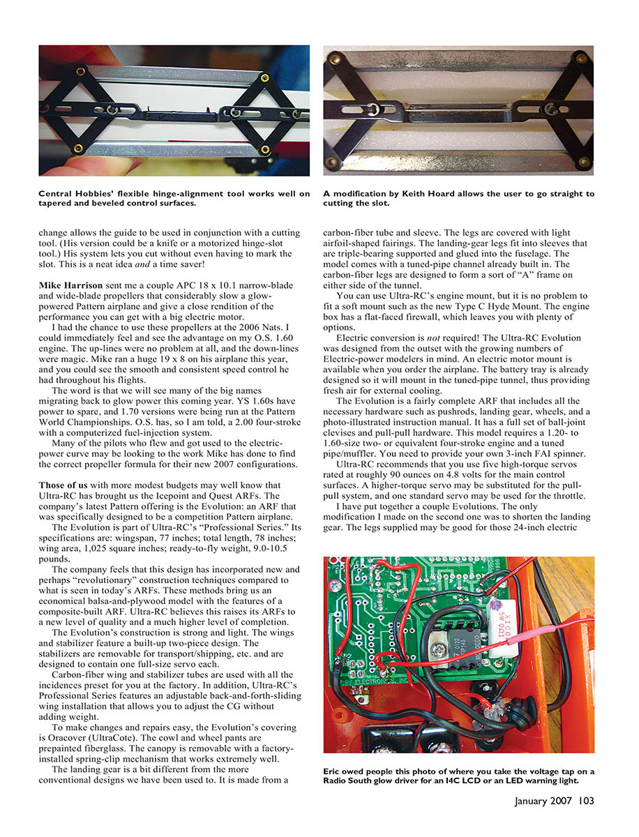
Central Hobbies markets a neat hinge-marking tool that enables you to make close-to-perfect hinge-slot alignment on straight, beveled, and tapered control surfaces. As is often the case, a Pattern-model builder will find a way to improve upon any device within reach. Keith Hoard sent me a picture of the modification he made to this hinge tool: he added an extra guide bar. His modification allows the guide to be used in conjunction with a cutting tool (a knife or a motorized hinge-slot tool). His system lets you cut without even having to mark the slot. This is a neat idea and a time saver!
APC propellers and glow power
Mike Harrison sent me a couple of APC 18 x 10.1 narrow-blade and wide-blade propellers that considerably slow a glow-powered Pattern airplane and give a close rendition of the performance you can get with a big electric motor. I had the chance to use these propellers at the 2006 Nats. I could immediately feel and see the advantage on my O.S. 1.60 engine. The up-lines were no problem at all, and the down-lines were magic.
Mike ran a huge 19 x 8 on his airplane this year, and you could see the smooth and consistent speed control he had throughout his flights. The word is that we will see many of the big names migrating back to glow power this coming year. YS 1.60s have power to spare, and 1.70 versions were being run at the Pattern World Championships. O.S., I am told, has a 2.00 four-stroke with a computerized fuel-injection system. Many pilots who flew and got used to the electric power curve may be looking to the work Mike has done to find the correct propeller formula for their new 2007 configurations.
Ultra-RC Evolution ARF
Those of us with more modest budgets may well know that Ultra-RC has brought us the Icepoint and Quest ARFs. The company’s latest Pattern offering is the Evolution: an ARF that was specifically designed to be a competition Pattern airplane. The Evolution is part of Ultra-RC’s “Professional Series.” Its specifications are:
- Wingspan: 77 inches
- Total length: 78 inches
- Wing area: 1,025 square inches
- Ready-to-fly weight: 9.0–10.5 pounds
Ultra-RC feels this design has incorporated new and perhaps “revolutionary” construction techniques compared to typical ARFs. These methods produce an economical balsa-and-plywood model with features of a composite-built ARF, raising the ARF quality and level of completion. The Evolution’s construction is strong and light.
Key features:
- Wings and stabilizer are built-up, two-piece designs. Stabilizers are removable for transport/shipping and are designed to contain one full-size servo each.
- Carbon-fiber wing and stabilizer tubes are used, with all incidences preset at the factory.
- Adjustable back-and-forth sliding wing installation allows you to adjust the CG without adding weight.
- Covering is Oracover (UltraCote) to make changes and repairs easy.
- Cowl and wheel pants are prepainted fiberglass.
- Canopy is removable with a factory-installed spring-clip mechanism that works extremely well.
- Landing gear is a carbon-fiber tube and sleeve design; legs are covered with light airfoil-shaped fairings. The gear legs fit into sleeves that are triple-bearing supported and glued into the fuselage. The model comes with a tuned-pipe channel already built in; the carbon-fiber legs form a sort of “A” frame on either side of the tunnel.
- Engine box has a flat-faced firewall, letting you use Ultra-RC’s engine mount or fit a soft mount such as the new Type C Hyde Mount.
- Electric conversion is not required but supported: an electric motor mount is available and the battery tray is designed to mount in the tuned-pipe tunnel for external cooling.
Included hardware and recommendations:
- The Evolution is fairly complete and includes pushrods, landing gear, wheels, a photo-illustrated instruction manual, a full set of ball-joint clevises, and pull-pull hardware.
- It requires a 1.20- to 1.60-size two-stroke or equivalent four-stroke engine and a tuned-pipe/muffler. You need to provide your own 3-inch FAI spinner.
- Ultra-RC recommends five high-torque servos rated at roughly 90 oz-in on 4.8 volts for the main control surfaces. A higher-torque servo may be substituted for the pull-pull system, and one standard servo may be used for the throttle.
Building and flight impressions
I have built a couple of Evolutions. The only modification I made on the second one was to shorten the landing gear. The legs supplied may be good for those 24-inch electric props, but they are a bit long for glow set-ups. I removed 2.5 inches and they worked fine with the O.S. 1.60 and 17-inch propellers.
My first build came out at 10 lb 9 oz, and my second came out at 10 lb 6.3 oz (with a 2500 mAh Li-Poly receiver pack, O.S. 1.60 FX, Karl Mueller header, and ES medium-length carbon-fiber 1.40 tuned pipe). The airplane goes vertical on half-throttle stick and is fully capable of doing all the F3A schedules.
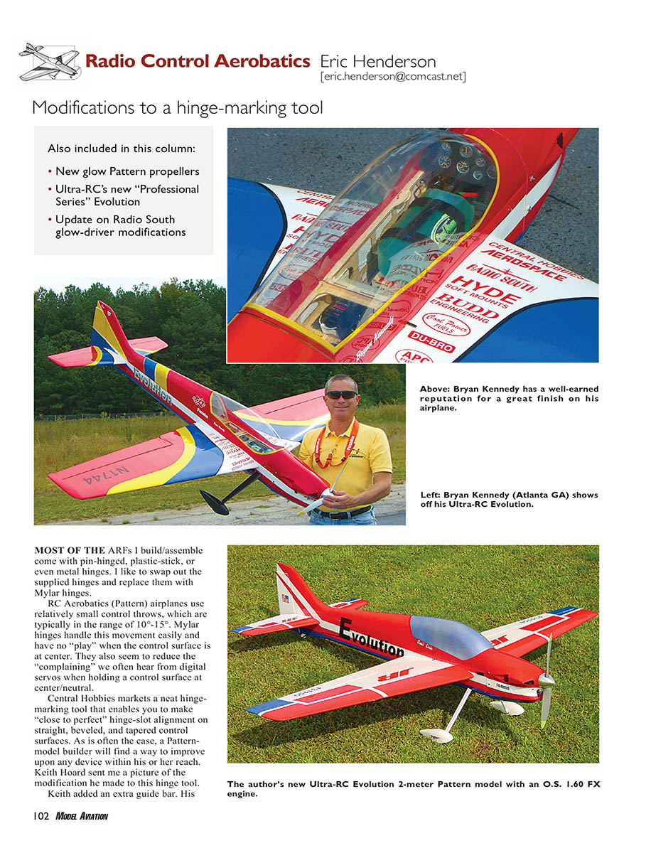
No sooner had I posted pictures of my model than Bryan Kennedy sent photos of his version. At first I did not recognize the airplane; it is amazing how just changing a few colors or patterns can make a model look so different. Bryan’s level of detail is way beyond any of my efforts. His version of the Ultra-RC Evolution came out at 9 lb 13 oz, making it a great home for his O.S. 1.40 RX.
Bryan reports spectacular vertical performance and nimble snaps that stop immediately. I found little or no coupling in the knife edge, depending on where I set the CG. The up-lines are straight, but at full throttle I had to add slight right rudder. My JR radio lets me dial 2% right rudder on only the last two clicks off the throttle ratchet. Once programmed, you can forget about needing any more rudder correction on the up-lines.
The down-line needed about 1.0% down-elevator at low throttle to get a perfect hands-off down-line. The knife-edge was strong and I reduced the rudder to low rate for snaps and spins. You have to go easy on the elevator when entering the spin or you may cause the “break” to occur too soon. It is a pronounced break and will leave the judge with no doubt that you performed a stalled entry into the spin.
Glow-driver voltage tap
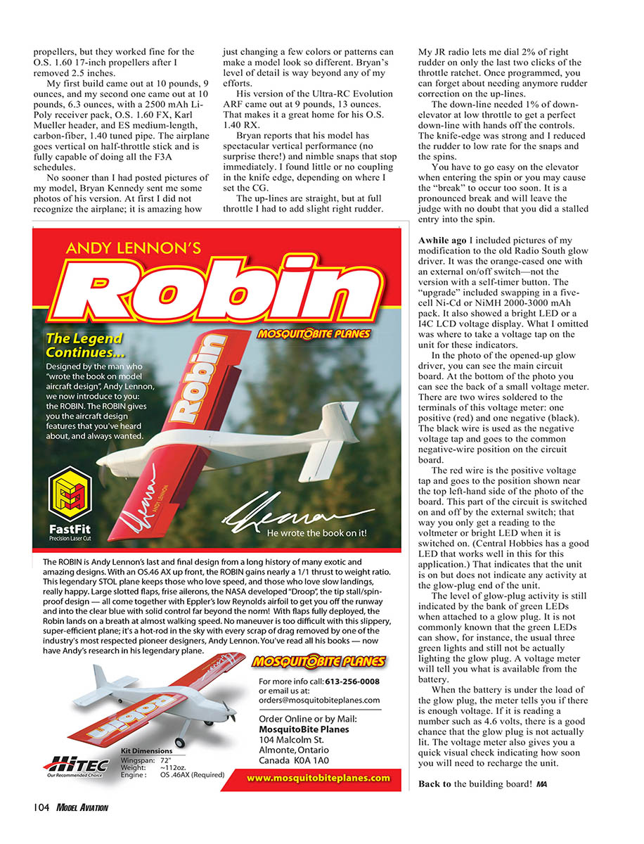
A while ago I included pictures of my modification to the old Radio South glow driver (the orange-cased one with an external on/off switch—not the version with a self-timer button). The “upgrade” included swapping in a five-cell Ni-Cd or NiMH 2000–3000 mAh pack and adding a bright LED or a 14C LCD voltage display. What I omitted was where to take a voltage tap on the unit for these indicators.
In the opened-up glow driver photo you can see the main circuit board and the back of a small voltage meter. There are two wires soldered to the terminals of this voltage meter: one positive (red) and one negative (black).
- The black wire is the negative voltage tap and goes to the common negative position on the circuit board.
- The red wire is the positive voltage tap and goes to the position near the top left-hand side of the board shown in the photo. This part of the circuit is switched on and off by the external switch so you only get a reading to the voltmeter or bright LED when the unit is switched on. (Central Hobbies has a good LED that works well in this application.)
That LED or meter indicates that the unit is on but does not indicate activity at the glow-plug end of the unit. The level of glow-plug activity is still indicated by the bank of green LEDs when attached to a glow plug. It is not commonly known that the green LEDs can show, for instance, the usual three green lights and still not actually be lighting the glow plug. A voltage meter will tell you what is available from the battery.
When the battery is under the load of the glow plug, the meter tells you if there is enough voltage. If it reads a number such as 4.6 volts, there is a good chance the glow plug is not actually lit. The voltage meter also gives you a quick visual check indicating how soon you will need to recharge the unit.
Back to the building board! MA
Transcribed from original scans by AI. Minor OCR errors may remain.

