
Radio Control: Aerobatics
Byline
Rick Allison 15618 NE 56th Way, Redmond WA 98052
Equipment installation and setup
We visited the question of building models versus buying them awhile back and examined the philosophical, moral, and practical angles, including the cost/benefit ratio. Whatever the source of the model, there is one thing almost all of us must do: buy it or build it, and then put our equipment in it and set it up properly.
Equipment installation and setup is the second-most-critical building step in determining how well a finished model performs, after fuselage/surface alignment and trammeling. Every servo hookup made, every cable run rigged, every control horn, mount, or support/retainer installed, is flight-critical. All of it should be as perfect as you can make it, because even a small mistake or miscalculation in this area can ruin your pride-and-joy.
Even small, nonfatal miscues, which are much more common, may have an effect entirely out of proportion to their perceived size. Every spring I'm called on to help trim unruly models at the local practice field. I often find that tiny setup errors are the only difference between an "off-board" keeper and an unfairly labeled "dog." When these "minor" items are pointed out to the owner as the source of the difficulty, the usual reaction is disbelief that something so insignificant could cause so much grief.
Aerobatic flight is an exercise in airborne geometric precision. In a fractal-like manner, this geometry repeats from macro to micro and back again in a very elegant and interconnected fashion. The models themselves are built around symmetry—measured and remeasured during assembly and rigged to (hopefully) exact angles of thrust and incidence. At the smallest scale, our control systems with their arcs, angles, and deflections repeat this obeisance to the geometric ideal. When something is awry at the upper level of this continuum, the cause very often lies below.
Control-horn geometry — a common source of trouble
I recall a nicely built Sportsman model whose owner was on the verge of mental instability because of severe loop-tracking problems. He had static-balanced the model, sealed the hinge gaps, weighted the supposed "heavy" wing, and shimmed the wing saddle—all to no avail. The first things I checked were the elevator control horns, and I found the source of the problem immediately.
As per standard practice, long 4-40 bolts and nylon horn ends had been mounted on dowel hard-points on both elevators. Both elevators trailed in perfect alignment in the neutral position—at least, so far as the pilot checked. However, airplanes don't loop with the elevators exactly neutral, and my friend had overlooked a simple geometry matter: the horns were misaligned.
One clevis attachment point was 1/16 inch in front of the hinge line on one elevator and an equal distance behind it on the other. In addition, the attachment point on one was 1/16 inch higher than on the other.
Control horns on matching surfaces, such as elevators and ailerons, must have matching clevis attachment-point heights and fore-aft displacements relative to the hinge line. Any deviation will cause unequal control-surface travel. If the attachment-point hole in the little nylon horn end is centered directly over the hinge line, the result will be differential travel up vs. down, because linear motion (pushrod or pull cable) is converted to rotary motion at the horn. The horn end travels through an arc; if the clevis attachment point is in front of the hinge line (with the pushrod below the surface), the pushrod geometry will result in more up travel than down. The converse is true if the attachment points are aligned aft of the hinge line.
Before the advent of computer radios and their myriad adjustment features, a simple technique was the common method of obtaining/adjusting aileron differential. In my friend's case, one elevator half was deflecting farther up than down while the other half was deflecting farther down than up, since the horn on the shorter side also deflected through a greater amount. Placing the elevators properly aligned in neutral revealed differences significant enough to amount to 45° of full travel. Several tweaks with a pair of pliers and a couple of turns on the lower horn end squared away the problem. We unshimmed the wing saddle and deweighted the wing; the model then tracked beautifully.
Servo geometry and matched servos
When separate servos are used on matched surfaces (common on ailerons and increasingly popular on elevators), the problem is compounded. The geometry at the horn ends must be precisely matched, but so must the geometry at the servo wheel or arm.
Servos provide rotary output motion, which is converted to linear motion via a cable or rod, which is reconverted to rotary motion at the control horn. The servo takeoff point travels in an arc on either side of neutral, as does the control-horn attachment point, with both points connected by a cable or rod of fixed length. Differential travel is now possible at either end of the hookup, and both the radius of the servo output arc and the radius of the control-horn arc are adjustable.
Treat the servo output wheel (or arm) as the "hinge line" at the servo end. At neutral, the arm or attachment point on the wheel should be perpendicular to the servo centerline, so the arc travel segments on either side of neutral are equal and the linear motion produced at the control horn is equal both ways.
In the pre-computer-radio era this ideal lineup sometimes took major fussing to achieve. Today's sophisticated equipment makes it easier—perhaps even too easy. There is a real tendency in the whiz-bang '90s to depend on electronics to totally exclude mechanical fixes. Servo not traveling far enough in one direction? No problem—adjust the radio. Too much travel both ways? No problem—adjust the radio. Surfaces not centered at neutral? Don't touch the clevis—just "beep, beep, beep" your troubles away.
The problem with that approach is the radio can never correct for poor mechanical hookup geometry in all conditions. For instance, my friend's elevator problem would never have been amenable to an electronic "fix."
Another common difficulty arises when separate servos must be matched, as in an aileron installation. A builder may choose to electronically limit or extend travel substantially on one or both servos rather than recenter or mechanically adjust an arm, with the result being travel equal on both servos but with differing transit times and trim rates. The result might be a subtle mismatch—a trim that "wanders" or a slightly different roll rate in one direction.
Recommended setup procedure
If you want to avoid electronic pitfalls, follow this route: make the mechanical setup as geometrically pure as possible, then use the radio to fine-tune.
- Start with a clean setup—never try to reuse a template from another model; the possibilities for confusion are enormous.
- Use the servo reversing feature to obtain the proper travel directions.
- Inhibit, activate, and assign all switches and set your fail-safe configuration.
- If your radio has a centering adjustment feature, set the servo centers to match and ensure the servo arm is perpendicular to the takeoff point.
- Make sure servos that serve matched surfaces are the same type, speed, and center.
- Make pushrod and cable length adjustments to obtain equal surface travel, using clevises and threaded ball links for fine mechanical adjustments.
- At the very end, use the radio centering feature only for very tiny final adjustments—less than about a half turn on the clevis or link.
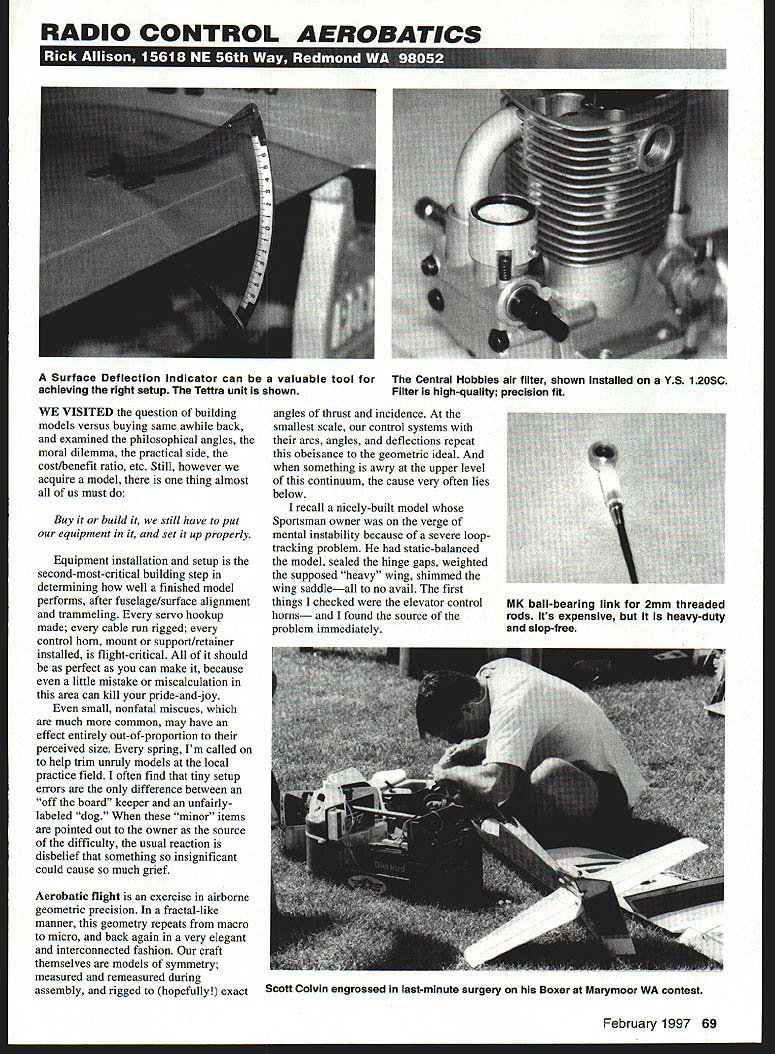
With the mechanical setup complete, check everything through the range of travel with one of the many surface-deflection indicators on the market. Pay special attention to painted surfaces, like ailerons and elevators. Absolute precision is nearly good enough—check it again, then re-check it. Now is the time to use the travel-adjustment feature to match travels in paired servos plugged into different channels.
At this point the basic setup is done and you can program rates, aileron differential, exponential, mixes, and the like, secure in the knowledge that there are no dark secrets hiding in the basement and identical things are happening on both "sides" of the airplane. The mixing programs and other sophisticated features of your radio will now work as intended and make much more sense.
New products
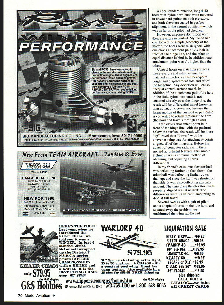
- Aluminum air filter for the YS 1.20: A beautifully made aluminum air filter that fits the NC, SC, and SF versions of the engine. It mounts securely with a single setscrew and claims nearly zero RPM drop and no transition problems. Marketed exclusively by Al Coomber of Central Hobbies in Billings, Montana. Price: $19.95. Contact: (800) 723-5937.
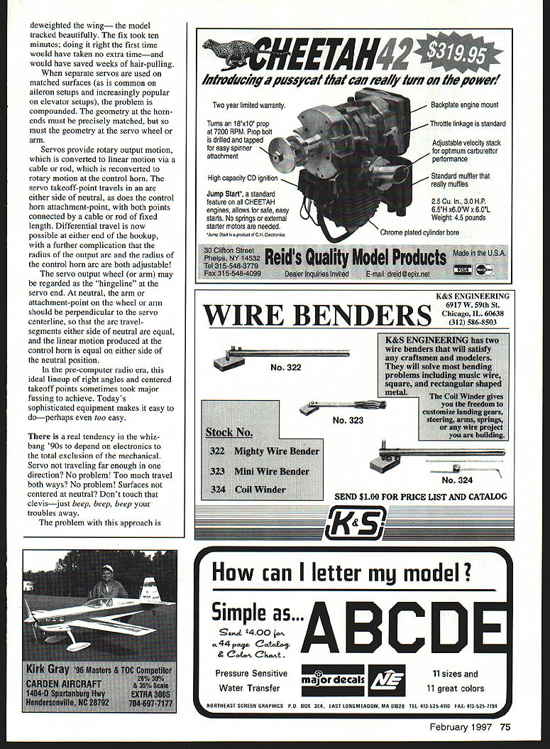
- MK ball-bearing link (part #0806): A heavy-duty, high-quality ball-bearing link for 2 mm rods. Average retail should be about $10 each (adjuster rod not included). This friction-free hookup device should be available wherever MK items are sold. The example shown was provided courtesy of Al Coomber at Central Hobbies.
Closing
Small mechanical items can and do defeat the best electronic cures. Aerobatics demands that the airframe and control systems be as close to geometrically perfect as practical. Spend the time to get the mechanicals right first; then use the radio to finesse only the fine adjustments.
Transcribed from original scans by AI. Minor OCR errors may remain.

