
Radio Control: Electrics
Bob Kopski
This is the inaugural "RC Electrics," and I am honored to have been asked by Model Aviation to write regularly. "RC Electrics" is basically intended to be a "how-to" column. As such, I'll try to offer useful and informative information each month to help make your electric-powered modeling more successful and more enjoyable — with understanding.
While there are a sizeable number of potential topics already lined up, I'd welcome inputs of the "how-to" nature from anyone willing to share their experience and accomplishments. I cannot say if, or when, any such offerings could be included here, but I'll do my best to accommodate as many as possible. Also, I'll probably be referencing various subjects in MA's 10-month Electric Series (September 1983–June 1984), so you may want to hang onto your copies.
Besides the "how-to," I'd also like to include some news of general electric interest, so please keep this in mind as well.
Finally, the column had to have a name, and "RC Electrics" fits right in an established MA format. Please don't feel left out if you have something of interest to offer in FF or CL.
Electric news
- A brand-new all-electric club has formed in Houston. President Ken Martin of the SPARKS (Silent Propelled Aircraft Radio Kontrol Society) can be reached at (713) 933-1688, or at 13106 Newbrook, Houston, TX 77072. Write and find out how to join, and tell him you read it in MA! Best wishes to the SPARKS — bet they don't lose a field on account of noise!
- The Keystone RC Club has scheduled its Fifth Annual Electric Fly for September 22–23 in Hatfield, PA (just north of Philadelphia). Write to Bob Kopski, 25 West End Dr., Lansdale, PA 19446 for details.
How-to: Making a good-looking motor mount
I'd like to kick off the "how-to" intent with some thoughts on making a good-looking motor mount for any size electric model you have in mind. Back in the January 1984 issue of MA, I sketched some motor mounting suggestions, and it's one of these that I'll expand upon here. This technique is directly applicable to many models and in particular is quite suited to an upcoming construction article (the Spectra). The method shown now accomplishes the same result as some shop-oriented procedures but uses tools anyone can access and requires only a minimal amount of extra work.
#### Tools and materials
- An old baseball bat (the unusual tool)
- Knife, razor saw, sandpaper
- Square, pins
- Epoxy (five-minute and slow-curing)
- Balsa sheet and triangle stock
- 1/64-in. plywood wing-skin (two thin strips)
- Wax paper
- Small screws, small nylon angles
- Plastic auto-trim tape (about 1/4-in. wide)
- Optional: cyanoacrylate (CyA) glue for small assembly strips
#### Overview
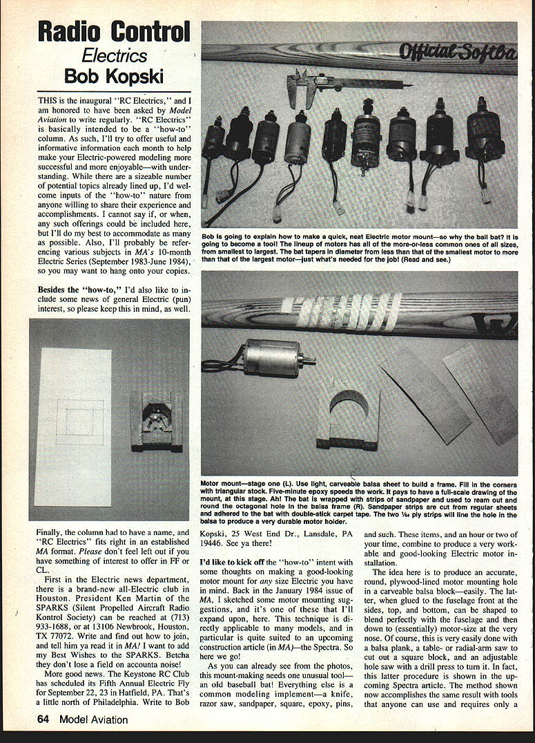
The idea is to produce an accurate, round, plywood-lined motor mounting hole in a carveable balsa block. The block, when glued to the fuselage front at the sides, top, and bottom, can be shaped to blend perfectly with the fuselage and then down to essentially motor size at the very nose. You can do this with a balsa plank and a saw and hole-saw, but the method here uses common modeling tools and a tapered baseball bat as a simple sanding reamer.
#### Procedure
- Determine the diameter of your motor. Add a bit more than 1/16 in.—say 3/32 in.—to this measurement. This is the size hole needed in the balsa block; it accommodates the motor and two wraps of 1/64-in. plywood wing-skin plus a bit for tape shim.
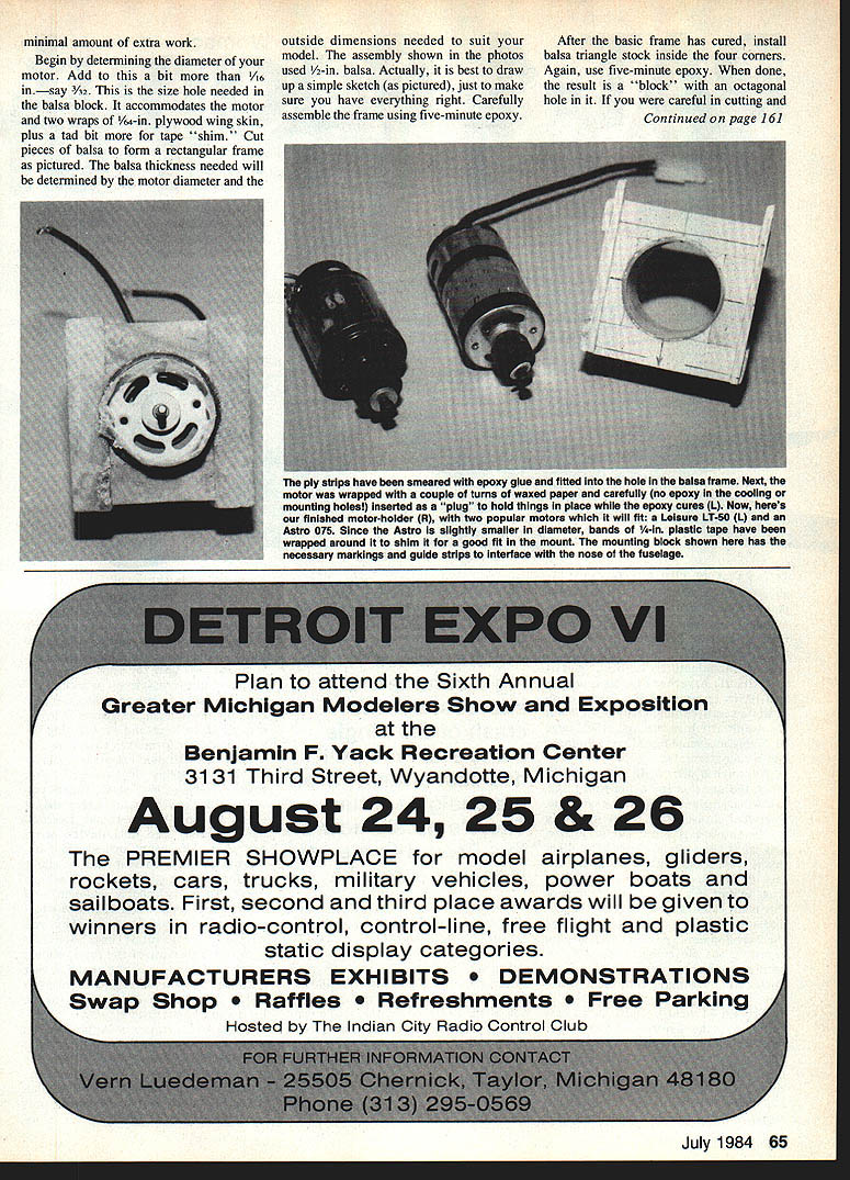
- Cut pieces of balsa to form a rectangular frame sized to the motor diameter and the outside dimensions needed to suit your model. The balsa thickness needed will be determined by the motor diameter and the outside dimensions. The assembly shown used 1/2-in. balsa. It is best to draw a simple sketch to make sure you have everything right. Carefully assemble the frame using five-minute epoxy.
- After the basic frame has cured, install balsa triangle stock inside the four corners, again using five-minute epoxy. The result will be a block with an octagonal hole in it. If you were careful cutting and fitting the balsa pieces, the assembly will be square on all sides and the motor hole will be parallel to the outer surfaces. When installed, the assembly will take on any desired thrust settings as may have been cut in the front of the fuselage—no angles have to be cut into the block.
- The inner dimensions of the octagonal opening should be such that the final desired round hole size results when the octagonal opening is rounded off. To do this, fashion a simple sanding tool from an old baseball bat: cut off the thicker handle portion and select the region of the bat where its diameter tapers to the desired size. Attach strips of sandpaper that extend slightly past this region. I used 120-grit strips about 3/4 in. wide and held them in place with double-stick carpet tape. Because the bat is tapered, the strips have to be wound in a spiral. This technique can accommodate most any motor size depending on the bat; I found one that fits motors from 02 to 40, as pictured.
- Ease your homemade sanding tool into the octagonal hole with a gentle pushing and twisting motion. The sanding tool will quickly round the octagon into a smooth, circular hole. Keep track of the hole size so you do not overshoot. Also consider the hole taper.
- Taper considerations:
- You can create a small taper depending on the bat's shape. A long gradual taper is best.
- You can sand a little from each side (a "switch-sander" technique) to produce a small total taper with a high spot in the middle; that high spot can be smoothed later and is seldom noticed.
- A straight taper from one end to the other will wedge the motor when inserted from the large-diameter side; the motor housing can be wrapped with tape to build up to the large opening. However, a straight taper can make liner installation trickier.
- Prepare the plywood liners: cut two strips of 1/64-in. wing-skin material. One should just wrap around the motor and close on itself (no overlap). The second should be slightly larger so it wraps around the motor plus the first piece and also closes on itself. The liners should be the proper width to fit from the front to the rear of the block.
- Trial-fit everything in the rounded hole. The motor should slide easily with the two liners in place. When everything fits, disassemble, and coat the larger outer skin generously with slow-curing epoxy. Curl it with the epoxy side out and slip it into the hole, working the epoxy so the balsa-ply interface is well coated. Locate the ply seam at the top or bottom of the hole.
- Coat the second (inner) liner with epoxy and insert it with the epoxy side out, locating its seam opposite the first layer's seam. Wrap the motor housing with two or three layers of thin wax paper and push it into the hole as a "plug" to press the liners snugly outward against the balsa. Wipe off excess epoxy and make sure none is on the motor. Set aside to cure. (At no point should the motor be fitted so tightly as to break the balsa frame—use care.)
- When cured, remove the motor and "face off" the ends of the motor block by rubbing them on a full-size sheet of sandpaper, rotating your grip frequently so the faces are flat. Mark any dimensions or alignment notches needed for mating with the fuselage.
- Glue small 5/16-in. square balsa assembly guide strips (or similar) inside the block to position the fuselage sides during attachment; I used CyA glue for these. These strips and excess block balsa will be carved away and sanded to shape. The very front of the mount can be shaped right down to the ply liner for an attractive finish.
- Actual motor attachment: use small screws that fit through small nylon angles into the front end-bell of the motor. Glue the angles inside the plywood motor tube. Use about 1/4-in.-wide plastic auto-trim tape wrapped around the motor housing to shim the motor to a slightly snug sliding fit in the hole.
For additional sketches and details see my January 1984 MA article; more illustrations will appear in the Spectra construction article.
For those enjoying electric flying, you can now easily enjoy good-looking electric installations as well.
Happy landings!
Bob Kopski 25 West End Dr., Lansdale, PA 19446
Transcribed from original scans by AI. Minor OCR errors may remain.

