
Radio Control: Electrics
Bob Kopski
Electric events (planned)
- International Electric Fun Fly — June 22–23, 1985; Ontario, Canada. Site about 55 miles from Niagara Falls. Contact: Vic Walpole, 102 Admiral Road, Ajax, Ontario L1S 2P1, Canada. Also contact Vic if you want to join an electric association. An opening symposium on electric propulsion is in the planning stages.
- Third Annual Boeing Hawks Electric Fly-In — Saturday, June 29, 1985; Kent, WA. Contact: Bernard Cawley, 210 37th St. S.E., No. 43, Auburn, WA 98002. Prizes for longest flight, most aerobatic, smallest airplane, and others. An electric clinic, conducted by Mitch Poling, is tentatively scheduled.
- South Shore RC Club, Inc. Electric Meet — Sunday, July 21, 1985. Contact: Charles Sylvia, P.O. Box 775, Middleboro, MA 02346.
- SPARKS Electric Meet — Houston, TX; August/September 1985 time frame. Contact: Ken Martin, 13106 Newbrook, Houston, TX 77072; (713) 933-1688.
- Sixth Annual KRC Electric Fly — September 21–22, 1985; Hatfield, PA. For information write: KRC Electric Fly, 140 Hopewell Ln., Telford, PA 18960.
Once again, I encourage small groups of electric fliers to organize local get-togethers. It doesn't have to be formal — call it a "Come Fly With Us!" and send me a copy of the flyer. I'll do my best to get it into the column if I receive it in time (it takes about three months from receipt to print). Also send info to the electric columnists in the other model magazines — they're good guys and will usually help promote your activity.
Electric publications and supplies
- Congratulations to Mitch Poling on the publication Building and Flying Electric-Powered Model Aircraft (Kalmbach Publishing Co., 11027 North Seventh St., Milwaukee, WI 53223). Price: $9.95 plus $1 postage. The 76-page book is filled with photos and covers nearly everything needed to build, fly, and enjoy electric models. Recommended for newcomers and experienced fliers alike.
- Belgium's Peter Blommaart has collected many fine articles from his magazine in a Compendium. Available for $17 postpaid from: Peter Blommaart, Ampere Flyer, P.O. Box 23, B-6200 Gosselies, Belgium. Annual subscription to Ampere Flyer is $25. Ampere Flyer also supplies products (including Unger motors) and accepts various credit cards. Tell him you saw it in Model Aviation.
- Former world champion R/C soaring pilot Dwight Holley has taken up electrics and plans to supply electric merchandise. He is researching availability worldwide and intends to carry a complete line at attractive prices. Write: Holley's Silent Flight, 151 Chestnut Ridge, Bethel, CT 06801.
Video
I don't know of any videotapes specifically on electric flying, but someone who filmed the 1984 KRC Electric Fly may have a good tape. If that person is reading this column, please drop me a line — we might arrange sharing. You may have the first-ever electric video!
Thanks and submissions
Thanks to everyone who has sent letters and pictures. Most photos are quite good and are easy candidates for inclusion, but I can't use everything because of the "how-to" photos I try to publish each month. I have a backlog of photos and topics, but I appreciate your inputs and will use what I can as space allows. Please continue to write and send photos. (You might even tell the Editor how much you enjoy this column and request more space!)
Motor versus radio
A tip from hard experience: some radios will "glitch" when the airborne system or transmitter is turned on. If you use a servo-activated on-off motor switch, take care: if your model does not have landing gear that gives prop clearance when on the bench, pick the plane up before turning on the radio. If a motor-control servo twitches and hits the switch, the prop can start spinning. A momentarily stalled motor can blow a system fuse or damage the switch. Switches are often not field-serviceable, so a little care prevents trips back home.
Range checks with electrics: a ground range check usually shows the familiar radio range with the motor off, but when the motor starts you can get glitching. Motor electrical noise can both introduce unwanted signals and reduce the receiver's ability to decode the transmitter — similar to listening to AM radio during an electrical storm or near a power tool. As a guideline, allow up to about 10–15% range reduction with the motor on; this is normally acceptable with modern radios. If you see worse degradation, inspect your installation.
Common causes of excessive radio noise:
- Untidy wiring where the receiver antenna passes between motor system wiring.
- Worn or damaged motor brushes and commutators causing excessive sparking.
- Electronic speed controls (ESCs) that are not optically coupled. Some receivers will not tolerate being connected to the motor power system wiring with non-isolated ESCs. Test by temporarily removing the ESC and operating the motor with a manual switch; if range returns to normal, the ESC-receiver combination is likely incompatible. Options: change radios or use an optically coupled speed control.
Speed controls — Jomar (SC-1, SC-2) and safety modification
Jomar (Joe Utasi) speed controls (SC-1, SC-2) are popular. By design, these controls can allow the motor to come on in the absence of a control signal. That means if you turn on the radio and motor systems without the transmitter signal present, the motor may come on. The same thing can happen when the plane flies through signal nulls: the motor can run wide open unintentionally. I had an incident where a visitor's transmitter went dead during taxi and the plane took off with full motor.
This situation can be corrected by adding a single resistor to the SC-2 (a safety modification). Joe is aware of this and can help. Think of it as a safety enhancement.
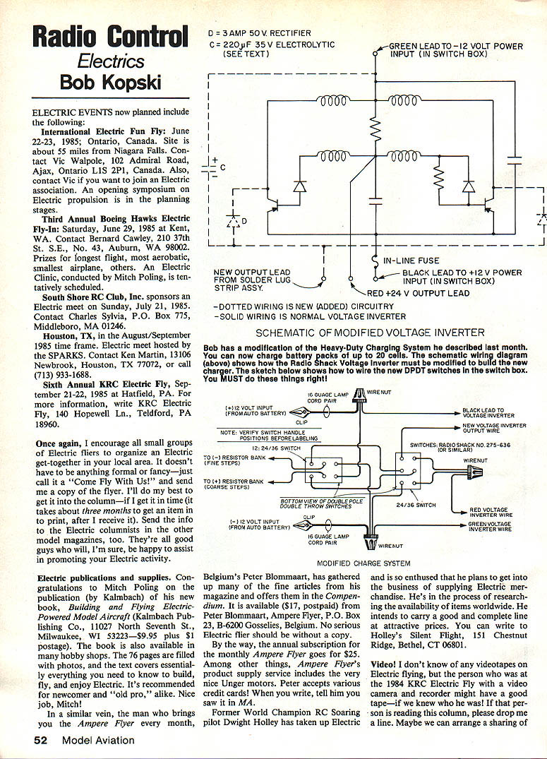
SCHEMATIC OF MODIFIED VOLTAGE INVERTER
Note: the original article included schematic drawings and photos of the modification described below.
Charge system modification (higher-voltage version)
Last month I presented a simple, nearly solderless charge system that would charge up to 14 cells. This month I describe a modification that extends the system so you can charge up to about 16 cells at full recommended current and more than 18 cells at reduced current. This higher-voltage version requires soldering — if you are not equipped or skilled, ask a friend to help. We're dealing with significant power, so assemble carefully and correctly.
Three minor modifications are required:
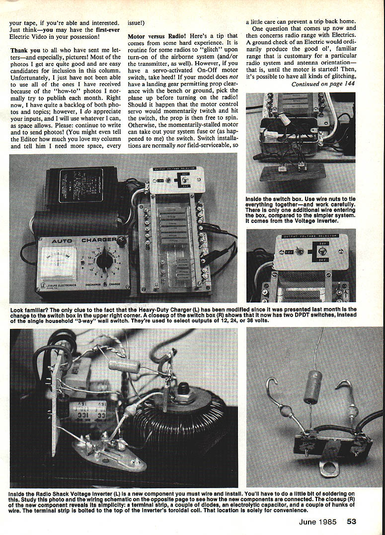
- Modify the Radio Shack Voltage Booster (Voltage Inverter) by adding two rectifier diodes, a capacitor, and an extra lead-out wire. These are mounted on a small terminal strip. This addition lets the inverter develop roughly 36 volts nominal from a 12-volt auto battery input — the trick to charging more than 14 cells.
- Replace the simple household wall switch with two double-pole, double-throw (DPDT) toggle switches in the switch/wiring box. The two switches are used in combination to select 12, 24, and 36 volt outputs which, with the resistor bank, determine the charge current. One switch selects the 12-volt option (or the other switch), and the second selects between 24 and 36 volts. Replace the original cover plate with a new mounting plate (aluminum, countertop material, or 1/8" plywood).
- Replace the original 8 amp in-line fuse of the Voltage Inverter with a higher value fuse (I used 15 amps). When fully loaded the unit can draw significant input current from the 12 V source (on the bench I observed input currents up to about 10 A). For safety, use the heavier fuse recommended. Be aware the inverter housing and resistor bank get hot in use.
Practical usage and limits:
- Recommended charge output current: do not exceed 3 amps for routine charging. This system will deliver a full 3 amps into 16 cells; it will deliver somewhat lower (less-controlled) current into 18 cells.
- Suggested voltage-position usage:
- 12 V position — charge up to 6 cells
- 24 V position — charge up to 12 cells
- 36 V position — charge past 12 cells (note: 36 V configuration does not regulate well; the voltage drops to near 30 V under load)
- Input-side caution: When the 12 V source is connected the system idles (even if no pack is connected) and the inverter will run. Input current at idle is low.
- The resistor bank and inverter housing will get hot — the inverter may reach ~60° C during heavy use. Keep the system out of direct sunlight to help cooling.
- Do not start your car or use the system with the car running. If your Astro or Leisure charger has a trickle-charge function, disconnect it — 36 volts is too much (even 24 V is pushing it). Ensure the Astro 4005D current adjustment knob is fully counterclockwise until it clicks before charging.
- Keep charge output leads from contacting the car body — they can be hot with respect to each other. Consider adding a master on-off switch in the positive input line.
Suggested charge currents and times for packs that are essentially "dead" (use as a guideline):
- 0.55 Ah — 2 amps for 15 minutes
- 0.8 Ah — 3 amps for 15 minutes
- 1.2 Ah — 3 amps for 20 minutes
I bench-tested this modified version for over two hours continuously with no problems. The resistor bank gets very hot as expected and the inverter housing becomes uncomfortably warm but within design limits. Earlier Astro 15 and 25 systems (each using 16 cells) remain perfectly usable; I've used a belt-drive 15 for six years.
Yet to come: more on charging large packs, including a sophisticated electronically-controlled charger with no resistor bank (for more demanding and skilled readers).
This system is based on the Radio Shack Voltage Inverter.
Other notes
- The "Basic Electricity" series has been temporarily on the back burner; I plan to resume it next month.
- Comments or questions may be forwarded to the author (with SASE, please).
Happy electric landings!
Bob Kopski 25 West End Dr., Lansdale, PA 19446.
Transcribed from original scans by AI. Minor OCR errors may remain.

