
Radio Control: Electrics
Bob Kopski
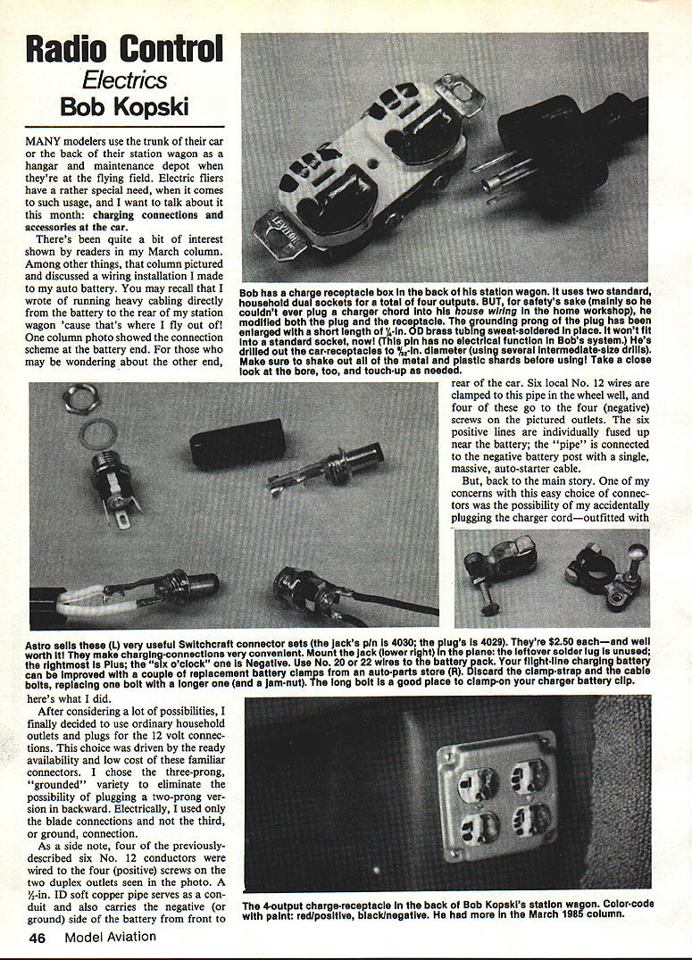
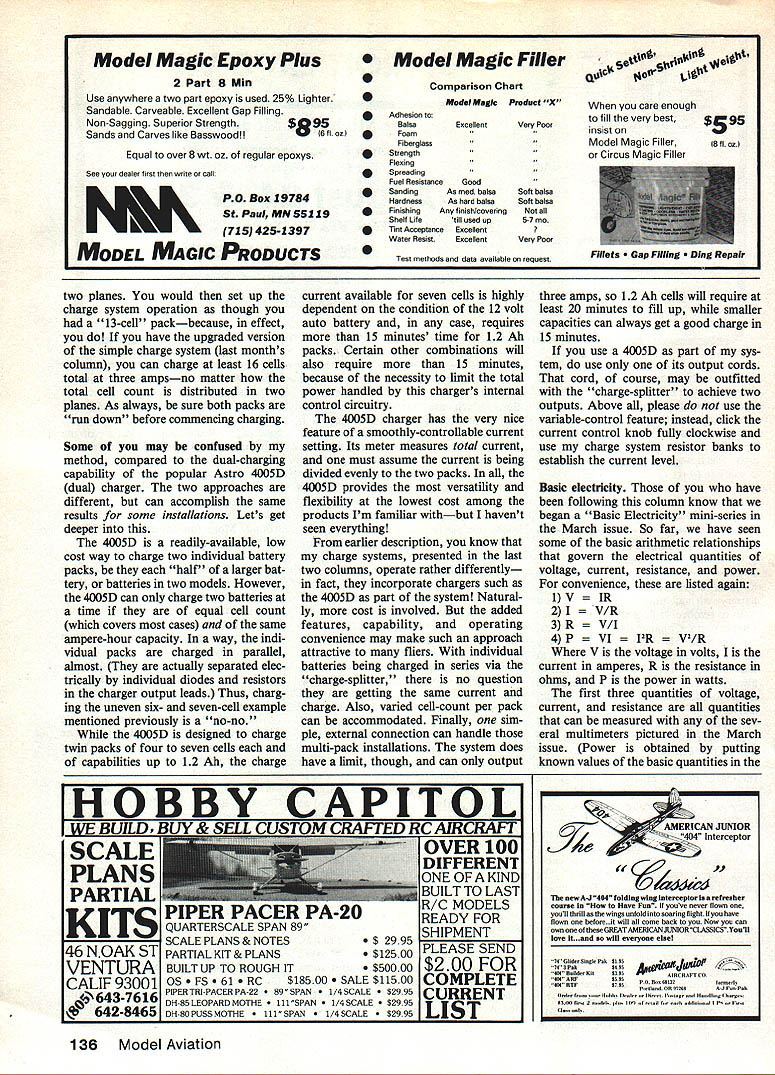
Many modelers use the trunk of the car or the back of a station wagon as a hangar and maintenance depot at the flying field. Electric fliers have a special need when it comes to such usage: charging connections and accessories at the car. This month I describe a wiring installation I made to my auto battery and the charging connectors and accessories I use in the car and on the planes.
Car charging connections and wiring
After considering many possibilities, I decided to use ordinary household outlets and plugs for the 12-volt connections. The choice was driven by ready availability, low cost, and familiarity. I used the three-prong grounded variety to avoid accidentally plugging a two-prong plug in backwards. Electrically, I used only the two blade connections and not the third (ground) connection.
Wiring summary:
- Four of the six No. 12 conductors are wired to the four (positive) screws on two duplex outlets (four positive outputs total).
- A 1/2-inch ID soft copper pipe serves as conduit and also carries the negative (ground) side of the battery from front to rear of the car.
- Six local No. 12 wires are clamped to this pipe in the wheel well; four of these go to the four (negative) screws on the outlets.
- The six positive lines are individually fused near the battery.
- The copper pipe is connected to the negative battery post with a single, massive auto-starter cable.
Plug and receptacle modification to prevent accidental household connection
One concern was accidentally plugging the car charger cord (with an ordinary three-prong household plug) into the house wiring at home. To make that impossible I modified both the plug and the car receptacle:
- I enlarged the grounding prong of the plug by sleeving it with a short length of 1/4-inch OD brass tubing and sweat-soldering it in place. That enlarged pin will not fit a standard household socket; in my system this pin has no electrical function.
- I drilled out the car receptacles to 1/2-inch diameter (using several intermediate-size drills). Be sure to shake out all metal and plastic shards and inspect and touch up the bore as needed.
- Some grinding of the metal contact fingers inside the receptacle may be necessary to allow the oversized plug pin to fit.
These changes make it essentially impossible to plug the modified charger plug into household wiring and make it unlikely that ordinary household devices would be plugged into the car outlets. Even if someone did accidentally apply 12 V DC to a 115 V AC device, the risk is generally minimal.
Charger connections on the plane: Switchcraft connectors
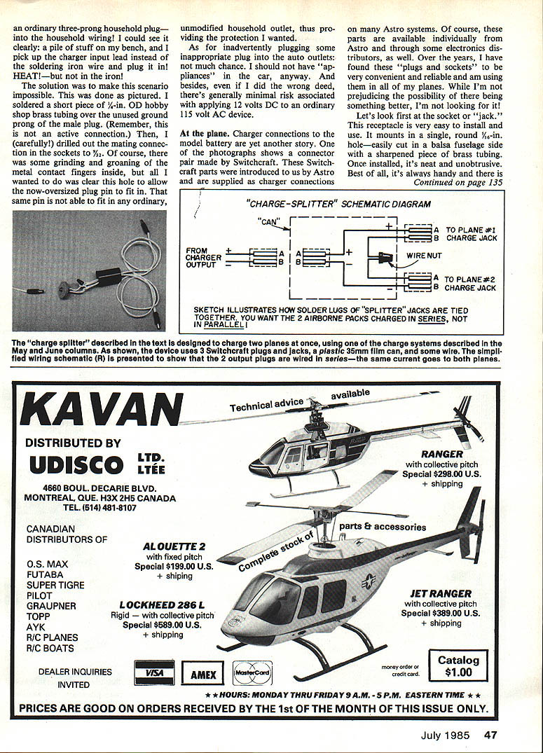
For the model-side charging connector I use Switchcraft plug-and-jack sets supplied by Astro (many Astro systems use these). I find them convenient, reliable, and durable.
Key points:
- The Switchcraft jack mounts in a single 5/8-inch round hole—easy to cut in a balsa fuselage side.
- Only two of the jack’s three solder terminals are used; the unused terminal can be nipped off.
- I normally route the two charge-jack wires directly to the motor battery rather than through the switch-harness, although the latter is acceptable.
- The male connector on my charger cords is compact, has two conductors, and is good for many hundreds of matings.
- My charger cords are white, 18-gauge lamp cord for visibility on the grass field, especially at dusk.
Molex connectors — use and limitations
Many systems supply two-prong plastic Molex connectors and use them for system wiring and charging. I view Molex connectors as better suited for infrequent connections (for example, motor to switch harness). For frequent connections such as charging, I prefer the Switchcraft parts.
Problems I've seen with Molex:
- When new the components fit tightly, but after numerous uses they can become mechanically flimsy.
- Repeated use can lead to degraded electrical contact and mechanical reliability.
- Gold-plated Molex versions may improve electrical contact, but the mechanical wear issue remains.
That said, some systems (for example, Astro 15 and 25) use Molex connectors by design because the battery is built as multiple smaller packs (six-packs or seven-packs) that are disconnected and charged individually. That arrangement allows convenient charging from a 12 V auto battery using a dual charger like the Astro 4005D.
Charging multiple packs without repeated Molex mating: a simple output-splitter
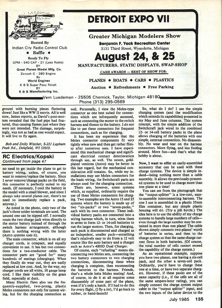
To avoid repeated Molex mating and to allow charging more than one plane at a time, I use a simple, low-cost interconnecting harness I call an “output-splitter.” The harness lets my charge system handle multiple packs (so long as total cell count and charger capability are not exceeded).
How it works:
- The splitter connects two planes’ charge jacks to a single charger output so the same charge current flows into both packs.
- This allows charging of two packs at once if the packs are of the same ampere-hour capacity (cell counts can sometimes differ depending on the charger topology—see the 4005D discussion below).
- The total number of cells connected must not exceed the capability of the charge system.
Parts and assembly:
- Two Switchcraft jacks (for the plane ends).
- One Switchcraft plug (for the charger end).
- A short length of twin-conductor lamp cord.
- A small length of brass tubing to sleeve the unused ground prong on the plug so it cannot make electrical contact.
- A small plastic container (I used a 35 mm film container; a pill bottle will do).
Mount the jacks in 5/8-inch holes in the container, solder the lamp cord to the jack terminals, and solder the cord to the plug as required. Sleeve the plug’s unused ground prong with brass tubing and seal the housing. The result is a rugged, inexpensive accessory that lets you charge two packs at once without disassembly or repeated harness mating.
Operational example:
- If you have two planes, one with a six-cell pack and one with a seven-cell pack, and both packs are of the same capacity (same ampere-hour rating), you can connect them to the output-splitter and charge both simultaneously from one charger—provided the charger supports the total cell count.
Comparison with the Astro 4005D dual charger
The Astro 4005D is a popular, low-cost way to charge two individual battery packs. It has useful features but also limitations:
- The 4005D can charge two batteries at a time only if they are of equal cell count and of the same ampere-hour capacity (covers most common cases).
- The charger output leads are separated internally (diodes and resistors), so the packs are effectively charged in parallel-like fashion; unequal cell counts (e.g., 6 and 7 cells) are not supported for simultaneous charging.
- The 4005D is designed for twin packs of four to seven cells each and up to about 1.2 Ah capacity.
- Available charge current (particularly for seven-cell packs) depends on the condition of the 12 V auto battery; some charge combinations will require more than 15 minutes for a 1.2 Ah pack because of the charger’s internal power limits.
- The 4005D has a smoothly-controllable current setting and a meter that measures total current (you must assume the current is divided evenly between packs).
My system vs. the 4005D:
- My charge systems (described in earlier columns) can incorporate a 4005D but operate differently: they charge individual batteries in series via a charge-splitter so each pack definitely gets the same current and varied cell-counts per pack can be accommodated.
- My system has a 3-amp output limit; at 3 A a 1.2 Ah cell will take at least about 20 minutes to fill, while smaller-capacity cells can get a good charge in around 15 minutes.
- If you use a 4005D as part of my system, use only one of its output cords (that cord may be outfitted with the charge-splitter). Do not use the 4005D’s variable-control feature—set its current control knob fully clockwise and use my charge-system resistor banks to establish the proper current level.
Basic electricity (mini-series recap)
We began a Basic Electricity mini-series in March. Some fundamental relationships are:
- V = I R
- I = V / R
- R = V / I
- P = V I = I^2 R = V^2 / R
Where V is voltage (volts), I is current (amperes), R is resistance (ohms), and P is power (watts).
Common prefixes:
- micro = 1/1,000,000 (10^-6)
- milli = 1/1,000 (10^-3)
- kilo = 1,000 (10^3)
- mega = 1,000,000 (10^6)
Application ranges in electric flight:
- Most batteries for our motors fall in the 4–20 volt range.
- Most motors (with suitable props) draw 5–25 amps; the majority fall in 10–15 amps and 6–16 volts.
- Motor input power ranges from about 20 watts (very small) to 500 watts (large); most of the commonly used setups fall in 60–250 watts.
If you don’t already own a multimeter, serious electric fliers will eventually find one invaluable. Many models and features are available; we’ll cover more of this in the mini-series.
Parts list (Radio Shack Voltage Inverter modification)
The parts numbers for the modification to the Radio Shack Voltage Inverter (described in last month’s column) were omitted previously. Refer to the Radio Shack parts in the lower right corner of page 53 in the June 1985 issue:
- Terminal strip (cut down from a five-junction): Radio Shack part no. 272-688.
- Two 50-volt, 3-amp rectifier diodes: Radio Shack part no. 276-1141 (note direction of the black-banded end).
- 220 microfarad electrolytic capacitor: Radio Shack part no. 272-1017 (negative lead goes to the terminal strip).
Electric event
SAM 76’s annual Old-Timer meet, scheduled for July 14, 1985, will include an Electric event for the first time. It’s a “no rules” (almost) event where the only requirement is that the model be a legal Antique or Old-Timer design; any electric power system is permissible. For further details contact Contest Director Ralph Biddle, 2156 Street Rd., Warrington, PA 18976.
Contact
Bob Kopski 25 West End Dr. Lansdale, PA 19446
Please forward any questions or comments (with SASE please) to the author. Happy electric landings!
Transcribed from original scans by AI. Minor OCR errors may remain.

