


RADIO CONTROL ELECTRICS
Bob Kopski, 25 West End Drive, Lansdale PA 19446
This column will cover some big USA/FAI news, some industry news, more motor alternatives, and more speed-control stuff.
FAI E-Power Meet (Australia, 1994)
Steve Neu, the man who dazzled hundreds at KRC in past years with his FAI electrics, called to tell me of the ’94 E‑Power FAI meet results.
This year's gathering of world competitors took place in Australia in November, and the results are very exciting: the U.S. team took second overall, with team member Jerry Bridgeman taking individual first place. Related big news is that the U.S. team was outfitted with custom Aveox brushless motors.
The team's motor controls were designed and individually built by Steve for extreme compactness. He tells me that the Aveox FAI motor and his motor-controller measure 90% efficiency at 3,000 watts on his dynamometer—an unheard-of achievement. Congratulations, team! And guess what? Some other international teams are now carefully studying brushless technology.
As an interesting sidelight, one competitive team had models outfitted with conventional motors and planetary drives. Gear drives are never used in these activities. In this case, however, the props were variable pitch and were controlled by a servo-driven pushrod running through the motor shaft and gear-drive assembly. The servo was commanded by a microprocessor that had sensor inputs from locations on the wing.
All this sophistication notwithstanding, the Aveox brushless motor technology was clearly superior. One giant attaboy to David Palombo (the man behind Aveox) for the know-how, conviction, and moxie to make it happen!
Industry News
- You may have seen the ads by EMS for Jomar speed controls. Joe Utasi has sold his speed-control business to EMS, who is now using the trade name Jomar.
- Many of you know Joe as the first to offer high-rate speed controls more than a decade ago—he established standard speed-control technology. Over the years, Joe continually expanded and improved his products and was always highly motivated to provide the very best. He's a familiar participant at the KRC meet, where he holds a reputation for helping anyone with a speed-control need.
- Joe is now pursuing other electronic things in life and tells me he is enjoying some newfound freedom that's allowing him to build and fly more—for a change! My sincere personal thank-you to Joe for his personal advancement of the electric art. I'm looking forward to flying with you, Joe, at KRC ’95.
Motor/Power System Options — Filling the Middle Ground
Last month I offered some thoughts about the low- and high-quality ends of electric motors and chargers. To review, I suggested that electric beginners who think they will stay with the hobby should seriously consider investing in high-end motor and charger products right from the start. Now I want to fill in the middle between the most economical and the most costly power systems with more options.
There is a class of motor/power systems best described as a "middle ground" product, and there are at least two established manufacturers of these products. In addition, many modelers "roll their own" versions in this category. I'm referring to power systems based on car motors (or derivatives) outfitted with gear drives, powered by six to ten cells, and typically turning relatively large folding props.
Established suppliers include:
- American Fun Fly Co., 7543 Maple Ave., Pulaski, NY 13142; Tel: (315) 298-3630 or (315) 676-4988.
- Model Electronics, 6500 6th Ave. NW, Seattle, WA 98117; Tel: (206) 782-7458.
From first‑hand experience and personal observations at flight demos, these alternative power systems are well worth considering for many electric applications. As a rough guideline, associated costs sit between the lowest- and highest-priced power-system products.
The motors are serviceable—meaning they are not "throwaways" like economy can motors. Some even offer features like adjustable brush angle, and there is a wide range of gear-drive ratios available.
So far, I've personally flown two versions of AFF systems in my REVOLTS and I have some Model Electronics products to try (but it's winter). I did, however, witness several flight demonstrations by Pete Peterson of Model Electronics at KRC ’94, and the performance was spectacular!
This was not exactly a surprise, because more than once I watched Daryl Sanford of American Fun Fly show his stuff too, and it's clear that one can attain impressive flight performance with such moderately priced equipment. I'm so enthused by all this that I'm planning a new model design especially for six-to-ten-cell power systems—but it will be a few months.
As for the "roll your own" crowd, several active e-modelers have caught on to the capability and affordability of geared systems based on car (or car-like) motors, and they routinely fly these in preference to all else.
Scott Hartman of Fritch, Texas, routinely uses a preferred car motor, gear drive, and prop. He has one in the photo-REVOLT! shown in one of the photos. (Scott is the designer of the Ace Puddlemaster.) Scott recently told me he substituted a Model Electronics system for one of his favorite "home brews" and, much to his surprise, found significantly improved performance.
Having my interest tweaked by such stories, I visited my local hobby shop and surveyed the car-motor department. What I found was frustration: there are countless car motors available that feature emotional names and not much other info on the box. Unless you're into experimenting, you might want to go with AFF or Model Electronics. These folks have done the dirty work of selecting the best options for motors and gears, relieving you of choosing between such tantalizing nomenclature as the "Super Ultra Turbo Motor Mania" and the "Mastodon Terminator."
These are all geared systems. The motors have very high-RPM winds that would (for the most part) be useless as direct-drive motors—the prop selection would be limited to very small props only, which are not too useful for most of our purposes. When combined with gear drives turning larger props, these motors afford much performance and flying fun.
Of course, not every model design lends itself well to a large prop or a large folding prop, so some judgment is required. I plan to have more detailed info on these product choices and applications in the future. For now, send for info from these suppliers and get a feel for what's available.
Speed Control Terms: Optocoupled vs. BEC
The February issue has been out for about two weeks, and readers are reacting strongly to the speed-control discussion therein. There is a lot of reader interest because many are experiencing glitching problems and because there is continuing confusion about two speed-control terms: optocoupled and BEC (Battery Eliminator Circuit).
The terms "optocoupled" and "BEC" are mutually exclusive. You cannot have both functions at the same time, although some controls offer you the user option of either. Here's the story:
- BEC means the speed control is equipped with the necessary electronics to power your receiver and servos from the motor battery. No receiver battery is needed. Power is derived and regulated from the motor battery and piped to your receiver/servos via the three-lead cable that connects the receiver to the speed control. This wiring also carries the receiver output signal to the speed control. It's a two-way street.
- Optocoupling means there is no direct electrical connection between the receiver system and the motor/power system—the same interconnecting three-lead cable notwithstanding. Thus you cannot power the receiver from the motor battery while at the same time being optocoupled.
How does an optocoupled speed control get control information if there is no electrical connection? Communication takes place via a light beam. Inside the optocoupler (which looks like a small IC) is a light-emitting diode and a light receiver (diode or transistor). The emitter sends light pulses (usually infrared) that represent the conventional pulses from a receiver, and the receiver converts these light pulses back to the electrical pulses needed to operate the rest of the speed-control electronics.
The main point is that there is no hard connection between the receiver wiring and the power system wiring. Just as no power can be carried from the motor battery to the radio via this "lighted path," so also is it much harder for power-system noise to be carried to the radio. The light commands travel only in one direction—from the light emitter to the light receiver. All this takes place in a sealed package, so you couldn't see the light beam even if it were in the visible spectrum.
Do you know if your speed control is optocoupled? It's easy to find out with a simple ohmmeter:
- With the speed control disconnected from everything, connect one ohmmeter probe to each of the three speed-control/radio receiver cable connector pins (one at a time).
- Connect the other meter probe to the speed-control motor or motor-battery connectors—one at a time. Try all combinations.
- If you have an optocoupled speed control, the ohmmeter will register "infinity" (open circuit) all the time.
- Repeat the test reversing the meter leads between the receiver cable plug and motor/battery connector positions to rule out polarity effects.
- If any connection combination causes a viable meter reading, then the control is not optocoupled.
There is, however, a small capacitance associated with the physical optocoupler and the printed wiring of the board it is mounted on. Usually this is about two to four picoFarads—representing several hundred ohms at 72 MHz. While optocoupling is very good at what it does, I have seen cases where some residual glitching (via this small capacitance) could be reduced or eliminated with the addition of chokes discussed last month—a sort of "double safety." I hope the above has cleared up some confusion and shared a few lesser-known bits of information.
Microprocessor-Control-Induced Glitching and Spectrum Photos
Continuing the discussion from the last three columns about microprocessor-control-induced glitching, several photos this month show the results of work done since writing the last column.
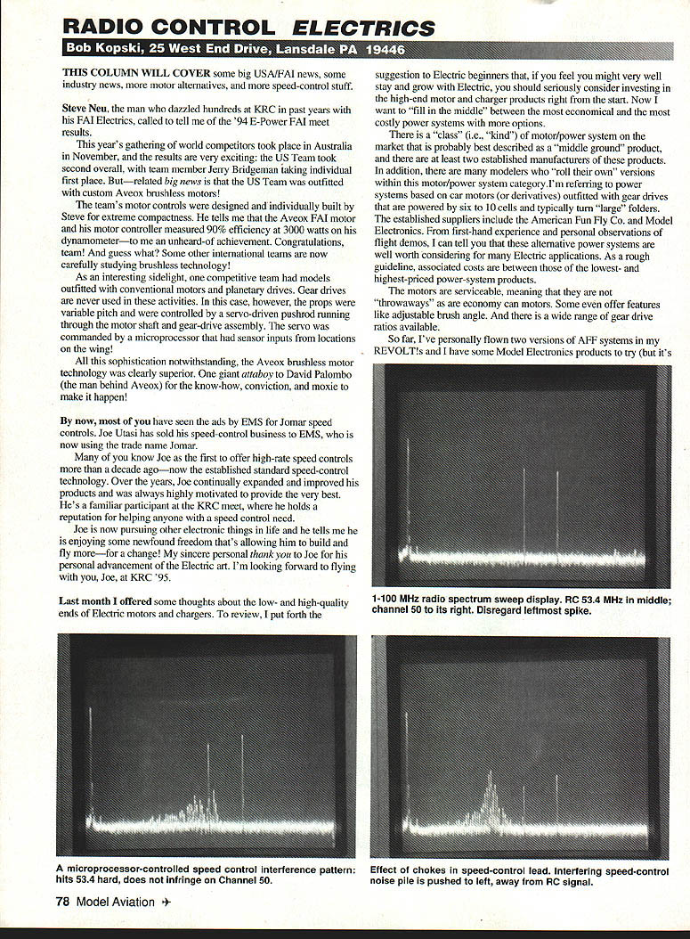
Photos One, Two, and Three are of my oscilloscope displaying the radio-frequency spectrum from about 1 MHz on the left to about 100 MHz on the right. In all the photos, the tall spike at the leftmost edge can be ignored; it's the zero beat of the spectrum-analyzer probe I was using.
- In Photo One, the spike near the middle is my 53.4 MHz RC signal, and to its right is my Channel 50 RC signal. These markers appear in Photos Two and Three as well so you can see what is happening and where.
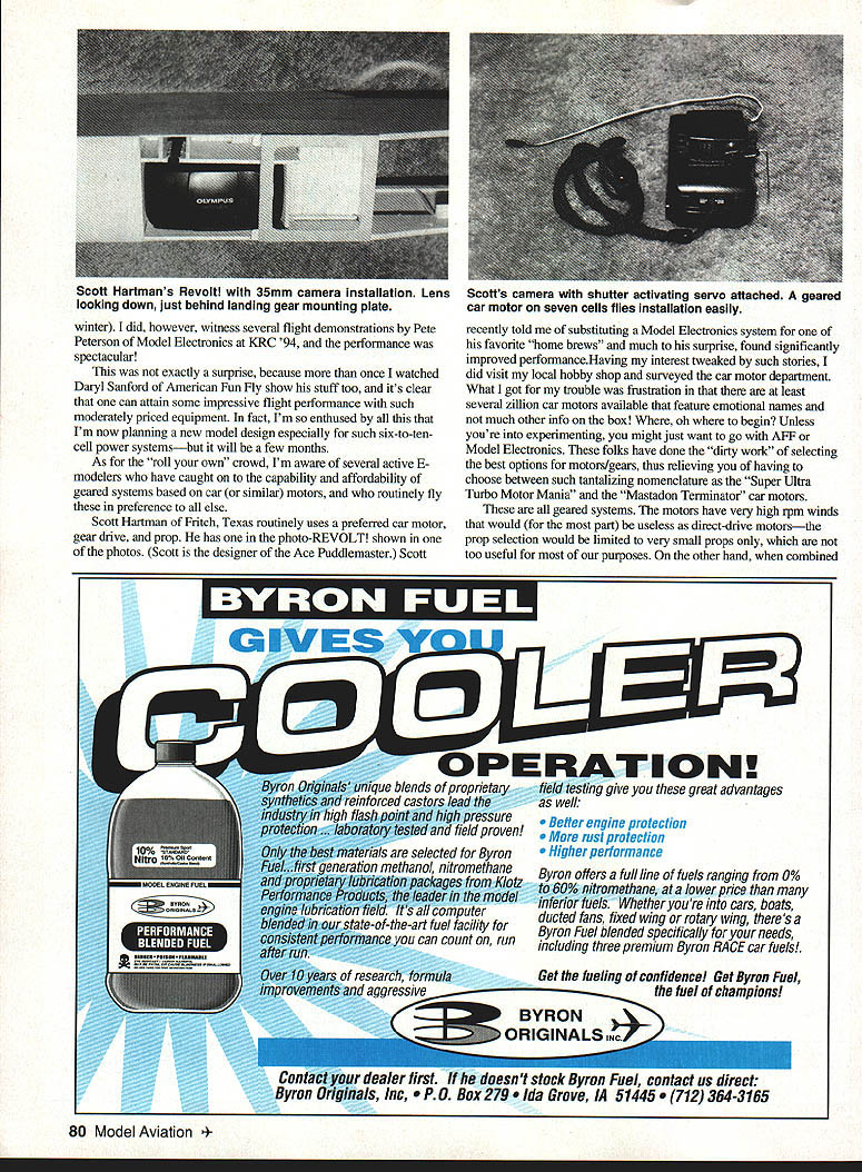
- In Photo Two, the large noise pileup is electrical "trash" (noise) on the receiver lead of a certain new reproduction speed control. This noise, caused by the microprocessor in the motor controller, clearly encompasses my 53.4 MHz RC frequency as interference and fully explains why I experienced lots of in-flight "hits" with this test product. Note that there is no junk showing near the Channel 50 marker.
- In Photo Three, observe that the trash pile is shifted to the left of my RC signal. This is the same speed control but now I've installed the chokes (discussed last month) in the control-to-receiver lead. This photo fully explains why/how the chokes work so well at reducing in-flight glitching. In effect, they stop the trash from extending into my RC frequency area. The noise energy is still present, but it piled higher at a lower frequency.
These photos also show why flying this control with 72 MHz equipment was nearly the same with or without chokes: there was no electrical junk at the 72 MHz spot anyway. Indeed, FM may have had nothing to do with the better performance I previously reported.
I have similar photographic data for several new speed controls and have been sharing this information with the various manufacturers involved. While the sample photos here show trouble at around 50 MHz frequencies, this sort of thing could happen anywhere—including the 72 MHz spots.
Given these observations, I've been encouraging manufacturers to invest in the low-cost Spectrum Probe to assist in product design. The photos I present were taken with a borrowed probe just to see what I could see.
Why am I doing this? It's all part of my electric aeromodelling fun; and in this case I've been told by some appreciative industry folks that this is all very worthwhile.
Closing
Please enclose a SASE with any correspondence for which you'd like a reply. Then go forth and enjoy the very best possible springtime electric landings, everyone!
Transcribed from original scans by AI. Minor OCR errors may remain.

