
RADIO CONTROL ELECTRICS
Bob Kopski 25 West End Drive, Lansdale PA 19446
This month's topics
- Electric Connection Service (ECS) Internet listing
- A "club call" for electric clubs and newsletters
- Reader query
- 1995 KRC Electric Fly Seminar schedule
- Continuing discussion of motor/prop/battery basics
Electric Connection Service (ECS) — Internet Listing
Ron Torrito, a longtime e-modeler in the Northern Connecticut Radio Control Club, asked about using the ECS to list Internet addresses to encourage communication among E-minded modelers. Sure!
First ECS Internet listing:
- R_Torrito@AOL.com
- Mailing address: 1625 Main St., East Hartford CT 06108
If anyone else wants their Internet address listed in the ECS, send it to me and I’ll include it in an upcoming column.
Club Call — Electric Clubs and Newsletters
I’d like to dedicate a future Electric Connection Service to listing all electric clubs. While I hope to document all clubs, I’m especially eager to know about clubs with membership openings so readers can join.
- Request: All interested electric clubs should write with suitable contact information by November 30, 1995.
- I will compile and present the listing in early 1996.
I regularly receive E-club newsletters from around the country; many are a treat to read and contain a lot of product and technical information. Some club newsletters dwarf a typical monthly magazine column. It would be nice to compile all that info into an annual "master newsletter" book.
If your club responds, please indicate whether newsletters are available to non-members, the price, and the mailing address for purchase.
Feedback Request
It’s very difficult for a columnist to please everyone. I try to include something for everyone over time, but I can’t always tell how the column is received. Some readers write with reactions; most are silent.
Much of this column’s content is my judgment, influenced by incoming mail, questions, and comments. I’d very much like to hear your specific interests, needs, likes, and dislikes about this column. Depending on your collective response, I’ll try to adjust the content to suit readers on average.
1995 KRC Electric Fly Seminar (preliminary schedule)
- Dates: Friday, September 15 (seminar 9 am–5 pm); Night flying begins about two hours after the seminar closes. Meet dates: September 15–17.
- Location: Best Western Motor Lodge, Quakertown, PA (about four miles from the flying field)
- Sponsor: SR Batteries
- Registration/reservations required; fee $15. Last year’s seminar was a sellout.
Scheduled speakers and topics:
- Micro-Electrics — Clyde Geist
- Electric Old Timers — Bob Aberle
- Rx/Tx Pack Care and Feeding — Larry Sribnick
- Computerized Radio Systems — Dave Baron
- Electric Flying — Tom Hunt
- Twin Motor Gear Drives — Clyde Geist
- Electronic Speed Controls — Martin Euredjian
- Getting the Most from Your Motor/Prop/Battery — Larry Sribnick
- Electric Night Flying — Bob Kopski
- Online Services/NEAC — Larry Sribnick
Contacts and mailers:
- Seminar registration: Larry Sribnick, SR Batteries, Inc., Box 287, Bellport NY 11713. Tel 516-286-0079, fax 516-286-0901. Send a SASE and you’ll get a five-page KRC Electric Fly mailer.
- Electric Fly Manager: Anthony Assetto, 639 Neshaminy Ave., Warrington PA 18976. Tel 215-491-9419.
Last year roughly 200 people witnessed an excellent night-flying display. Don’t dilly-dally — register early.
Motor/Battery/Prop Basics — Continued
Many modelers are puzzled by motor terminology and the makeup and operation of motors. Common questions include armature windings, turns, motor magnets, and proper voltage. Here’s a look at conventional brushed motors. Brushless motors will be covered later.
Motor basics — field magnets and magnetic circuit
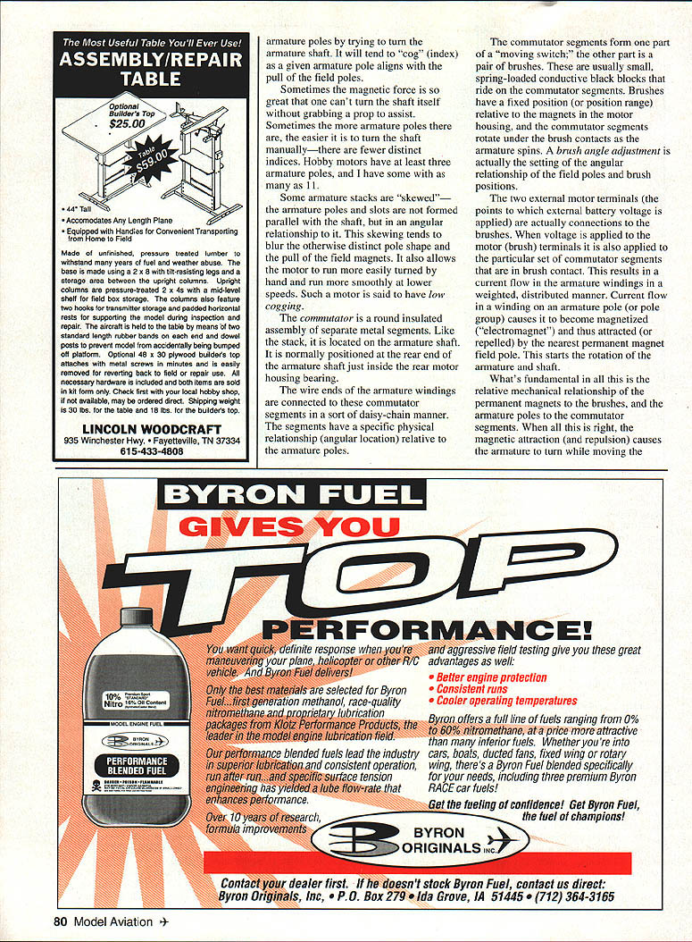
- These motors use permanent field magnets mounted in the motor housing (also called field poles). The magnets typically conform to the inner housings and form an empty cylindrical space for the armature.
- Most motors have two magnet assemblies producing diametrically opposed north and south poles.
- The individual field pole magnets are connected magnetically by the iron motor housing; this forms the magnetic circuit.
- Many motors have openings in the housing for cooling and to view internal parts.
Stronger magnets (for example, cobalt vs. ferrite) produce more flux and, all else equal, more torque. Higher flux lets a motor turn a larger prop slower and with lower current. Conversely, weaker fields can allow higher unloaded rpm but with less usable torque.
Extra flux rings (iron tubes that slip over the housing) can improve the magnetic circuit by thickening the housing and increasing flux inside the motor. This is beneficial mainly when the original housing is relatively thin.
The armature — structure and windings
- The armature is the rotating assembly mounted on the motor shaft and sits inside the magnetic field without touching the field magnets.
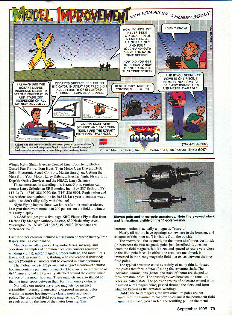
- Typical armatures are stacks of thin laminated iron plates shaped to form poles; the spaces between poles are called slots.
- Armature poles or pole groups are wound with insulated magnet wire passed through the slots; these are the armature windings.
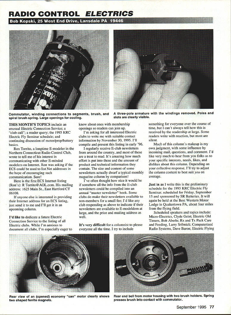
- The wire ends of the windings are connected to commutator segments mounted on the armature shaft.
Note: The iron armature poles are not permanently magnetized. You may feel attraction between the armature assembly and the field magnets when moving the armature, but this is simply attraction between iron and permanent magnet poles, not magnetization of the armature.
Cogging and skew
- If you try to turn the armature shaft by hand, the motor will usually "cog" (index) as armature poles align with the field poles.
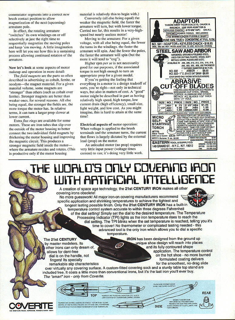
- Motors with more armature poles tend to cog less distinctly and are easier to turn manually. Hobby motors typically have at least three poles; some have as many as eleven.
- Some armature stacks are skewed — the poles and slots are formed at an angle to the shaft. Skewing blurs the distinct pole pull, reduces cogging, and makes the motor run more smoothly at lower speeds (low cogging).
Commutator and brushes — the moving switch
- The commutator consists of copper segments insulated from each other and mounted on the armature shaft (usually at the rear).
- Brushes are spring-loaded conductive blocks that ride on the commutator segments and provide current to the armature windings in sequence.
- The angular relationship of brushes relative to the field poles is important; brush angle adjustment sets this relationship.
- The two external motor terminals connect to the brushes. Applying voltage to those terminals energizes the commutator segments in brush contact and causes current to flow through the appropriate armature windings.
- As the armature turns, the commutator and brush interaction sequentially switches windings on and off at the right time to sustain rotation.
Motor design tradeoffs — turns, poles, torque, speed, and cost
- For a given voltage, fewer turns of thicker wire generally produce higher rpm but lower low-speed torque; more turns produce lower rpm but higher torque.
- Fewer armature poles generally increase rpm but worsen cogging; more poles reduce cogging.
- A "good" motor is a design compromise: relatively high speed, high torque, low current drain (high efficiency), small size, light weight, and low cost — and achieving all simultaneously is difficult.
- Stronger field magnets help lower rpm and increase torque, which can be beneficial when fewer winding turns are used.
Electrical aspects — voltage, current, and load
- When voltage is applied and the armature turns, current draw is largely dictated by the external load (the prop).
- An unloaded motor (no prop) requires little input power; adding a prop increases current demand because work is being performed.
- Motor rpm is roughly proportional to applied voltage; increasing voltage increases rpm, but even a small voltage increase can produce a larger increase in current.
- In practice, adding one cell to a battery pack can significantly increase power if the motor can handle the extra voltage.
- Real motors have losses (inefficiencies) due primarily to resistance in brushes, brush/commutator contact, and armature windings. These losses cause heating and mean rpm will drop somewhat under load.
- There is temptation to use massive brushes, large commutators, and as few turns of thick wire as possible, but fewer turns produce very high rpm and usually require gear drives or stronger magnets to make effective thrust.
Practical observations
- High-speed car motors used with large-ratio gear drives are popular for turning large props; alternatively, stronger magnets can be used to reduce rpm and increase torque.
- Every change is a tradeoff; practical limits on materials, size, weight, and cost govern what can be achieved.
Closing
I hope this look at motors gives you a better feel for how they work and differ. Upcoming columns will cover motor operation and application, cell count, and some influences of prop choice.
Please include a SASE with any correspondence for which you'd like a reply. Happy, quiet, E-power landings to you all.
Transcribed from original scans by AI. Minor OCR errors may remain.

