

RADIO CONTROL ELECTRICS
Bob Kopski, 25 West End Drive, Lansdale PA 19446
THIS MONTH'S TOPICS include a reminder ("Club Call"); an October meet; tiny R/C Electric gear; Master Airscrew product use and modifications; prop balancing; and follow-up on the electrified Sig Wonder.
Club call
- All-electric clubs (or clubs with significant electric participation looking to grow) are invited to write for listing in the early 1996 column.
- Clubs with electric newsletters that are available to anyone should indicate availability and how to obtain a subscription.
- Please include a SASE with correspondence for which you'd like a reply.
October meet — Gulf States Electric Fly-In
- Dates: October 21–22.
- Sponsored by: Ozone R/C Club.
- Location: Louisiana Polo Field ("America's Finest Electric Flying Field").
- Events: All-day fun flying, several contest-style events, Cajun cookout, and more.
- Contact: Ben Mathews, 101 Mulberry, Metairie LA 70005; Tel.: (504) 833-5589.
Tiny R/C Electric (CETO system)
- Cloud Nine RC (John Worth) is marketing a very small RC system by CETO — about 1/2 ounce airborne weight.
- John Worth (former AMA Executive Director) has described several indoor projects using this tiny system and is expanding its applications.
- Contact: Cloud Nine RC, 4326 Andes Dr., Fairfax VA 22030; Tel./fax: (703) 273-0607.
MASTER AIRSCREW POWER SYSTEM AND MODIFICATIONS
System description
- Master Airscrew economy electric power package typically includes:
- "Can" motor
- Gear drive
- 12 x 8 folding prop
- Spinner
- Available gear ratios: 2.5:1, 3:1, and 3.5:1.
- Typical price: often discounted under $30 (suggested retail $39.95).
- Operates well on 6–7 cells and offers good value for the money; used successfully in sailplanes (e.g., Electra) and some profile models (Mirage, PT Electric).
Issues encountered
- On some models the landing gear does not provide clearance for the supplied 12-inch folding prop, requiring hand launches.
- Folded blades can hang up on fuselage protrusions and fail to reopen.
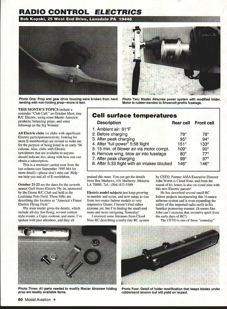
- In raffle/ready-to-fly applications (Showvolt/profile Revolt type), fixed-blade wood props (11 x 7 to 12 x 8) perform well but are often stronger than the supplied gearbox, resulting in damaged gearboxes after impacts.
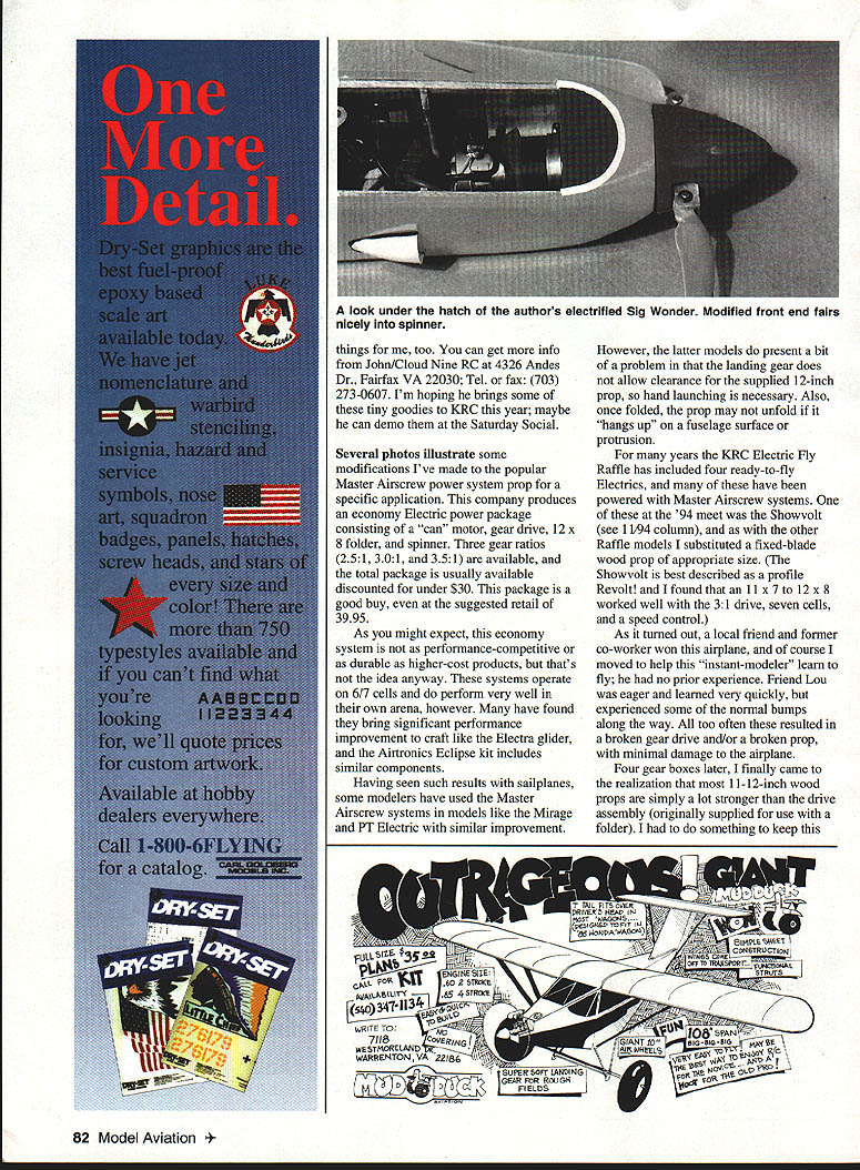
Motor mounting modification
- Purpose: let the motor assembly give under impact to reduce gearbox breakage.
- Change: retain original fuselage location and V-block, but replace the "golden inner rod" clamps with ordinary rubber bands to allow some movement.
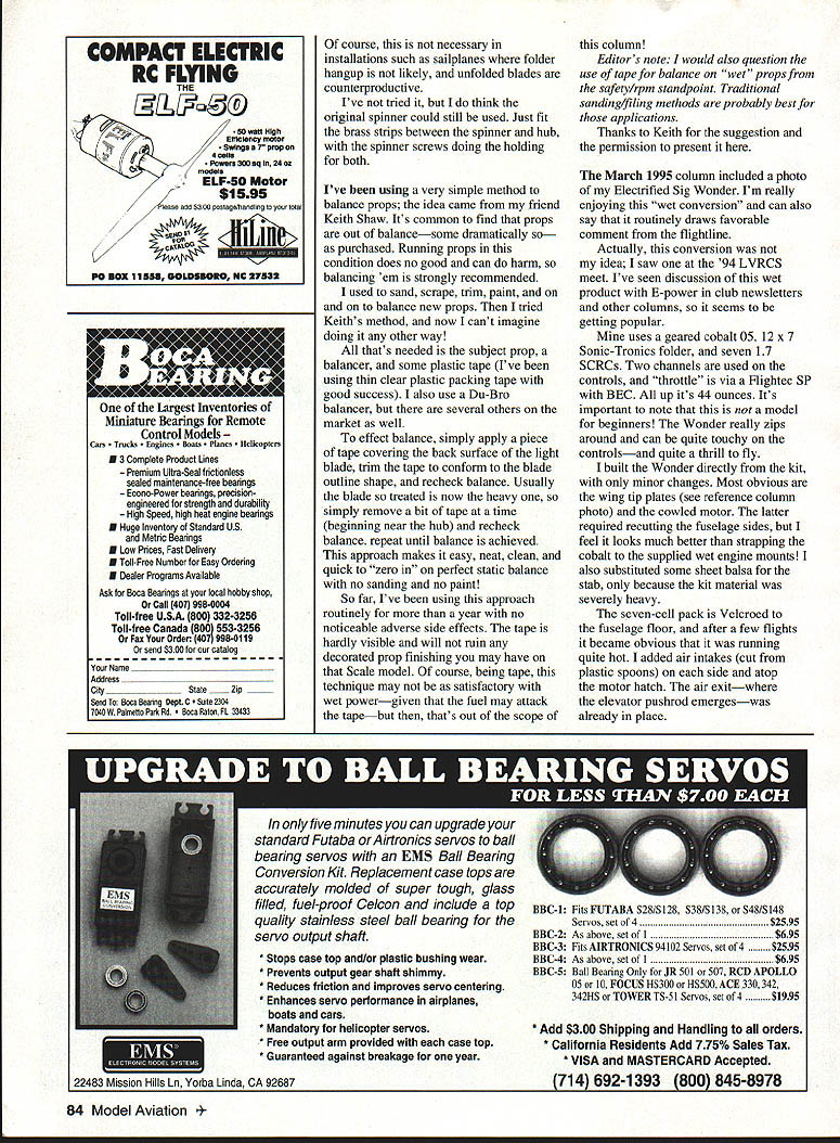
Folding-prop modification (prop-specific)
- Purpose: make folder blades springy, less likely to hang up, and able to yield on impact.
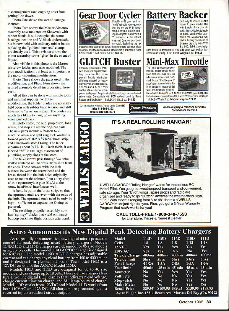
- Parts required:
- 1/4-inch length, 6-32 machine screw (quantity as needed for hub)
- 6-32 split-ring lock washer(s)
- Formed piece of .025" x 1/4" K&S brass strip
- Hardware-store O-ring (approx. 3/8" I.D., .1" thick — often labeled "#10")
- Small drop of thin cyanoacrylate (CyA)
- Steps (summary):
- Drill 7/64" holes centered on the brass strips, 1/8" from the ends.
- Pass 6-32 screws through these holes; place the lock washers between screw heads and brass strips.
- Thread the screws into the hub holes originally used for the spinner. Put a tiny drop of CyA at the screw head/brass interface.
- Bend the brass strip so the upturned ends are even with the hub ends; upturn only about 1/16" to capture the O-ring.
- Fit the O-ring over the upturned ends to hold the blades in the open position under light tension; blades gain a springy give on impact.
- Notes:
- This modification can be done with simple tools and supplies.
- The original spinner may still be usable by fitting the brass strips between spinner and hub with the spinner screws holding both.
- In sailplane installations where folded hangup is unlikely, this modification may be unnecessary or counterproductive.
PROP BALANCING
- Method (from Keith Shaw):
- Tools: prop, prop balancer (e.g., Du-Bro), thin clear plastic packing tape.
- Procedure:
- Mount prop on balancer and determine the light blade.
- Apply a piece of tape to the back surface of the light blade, trimmed to the blade outline.
- Recheck balance. If the treated blade becomes heavy, remove small amounts of tape starting near the hub and recheck until balance is achieved.
- Advantages:
- Quick, neat, clean, no sanding or paint required.
- Tape is nearly invisible and won't ruin decorated props for scale models.
- Caution:
- For "wet" (fuel) applications, tape may be attacked by fuel and is not recommended; traditional sanding/filing is probably best for fuel engines.
- The editor also questions tape use for high-rpm or wet props from a safety standpoint.
SIG WONDER ELECTRIFICATION — FOLLOW-UP
Conversion details
- Noted at LVRCS '94; became a popular wet-to-electric conversion.
- My installation:
- Motor: geared Cobalt .05
- Prop: 12 x 7 Sonic-Tronics folding prop
- Batteries: seven 1700 mAh SCRC cells
- Control: two channels; throttle via Flighttec SP with BEC
- All-up weight: 44 ounces
- Comments:
- The electrified Wonder is not for beginners — it is responsive and can be touchy.
- Built from the kit with minor changes: wingtip plates and cowled motor (required recutting fuselage sides), and substituted sheet balsa for the stab where kit material was heavy.
- Battery pack velcroed to the fuselage floor.
Cooling and battery-pack issues
- After several flights the pack ran hot; added air intakes (cut from plastic spoons) on each side and atop the motor cowl. Air exit was at the elevator pushrod opening.
- Cooling was only partially effective because the pack is nested; rear cells did not benefit as much.
Cell surface temperature tests
- Setup: LM34DZ sensor attached to a front cell and a rear cell; recorded surface temperatures.
- Results (rear cell / front cell):
- Ambient air: 81°F
- Before charging: 79° / 78°
- After peak charging: 95° / 94°
- After "full power" 5:58 flight: 151° / 133°
- 15 min. of blower air via motor compartment: 109° / 90°
- Remove wing, blow air into fuselage: 80° / 77°
- After peak charging (second measurement): 99° / 97°
- After 5:33 flight with air intakes blocked: 146° / 146°
- Observations:
- Cooling airflow as implemented may carry heat from the front toward the rear, making rear cells hotter.
- This does not compare with installations where airflow is planned from the start and is more effective.
Recommendations and notes
- Consider an E-configuration with a removable bottom hatch for cooling and easier recharging of the pack.
- Balance point is sensitive; honor the plan location. On mine the balance point is 5/8" forward of the plan location to calm the model. Do not balance rearward of the plan location.
- The Velcroed pack allows easy fore/aft adjustment for trimming.
- Reinforce the twin-fin attachment joints with triangle gussets where the fins meet the fuselage; the stock joints can break easily due to limited glue area and ground contact.
CLOSING
- Please enclose a SASE with correspondence for which you'd like a reply.
- Meanwhile, enjoy the clean, quiet, and powerful joy that electric flight brings — and the flying fields you don't lose because of it.
Transcribed from original scans by AI. Minor OCR errors may remain.

