


RADIO CONTROL ELECTRICS
Bob Kopski, 25 West End Drive, Lansdale PA 19446
Sermos economy connector
John Sermos, the modeler behind Sermos connectors, has announced an addition to his well-regarded connector product line. Sermos now offers an economy connector version selling for $1.80 for a standard 4-pack (two connector pairs). This is about half the price of the "high-end" Sermos connectors. The economy version is a standard Anderson part and uses the same basic interchangeable plastic housing and contact assembly that Sermos has custom-manufactured by Anderson.
You can obtain all versions from:
- Sermos RC Snap Connectors, Cedar Corners Station, Box 16787, Stamford CT 06905.
Refer to the September 1996 column for a discussion of these connectors, including the relatively new high-current contact version announced last summer.
Anderson Powerpoles comparison
Anderson sells the basic version of this connector under its own trade name, Anderson Powerpoles. Although some modelers use Powerpoles believing they are the same as Sermos-brand versions, there are important differences:
- Silver plating:
- Powerpole: 50 microns
- Sermos: 250 microns (custom)
- Specified contact resistance:
- Powerpole: ~600 microohms
- Sermos: ~250 microohms
- Mating-cycle life:
- Powerpole: ~2,000 cycles
- Sermos: ~100,000 cycles
It’s the old "you get what you pay for" story.
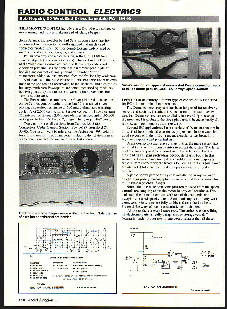
Deans connector safety warning
A different connector type commonly used for receivers, servos, and related components is the Deans connector system. Deans have been used in RC for well over two decades and are available in several pin counts. The most-used is the three-pin version (used by most radio system components). They have generally worked well in hobby electronics.
However, Deans connectors present a potential hazard: the male section has pins that protrude beyond the plastic body, while the female contacts are contained within a plastic housing. This leaves bare pins exposed on the male half. I photographed a disconnected Deans connector in my Aerovolt installation showing the male pins dangling near motor battery cell terminals. I have had such pins brush one of the cell ends and, phoof! — one fried speed control. This type of mishap is much less likely with connectors whose contacts are fully enclosed in plastic shells. Be wary of this potentially costly danger.
Electronic parts — "smoke storage vessels"
An old description I once read called all electronic parts "smoke storage vessels." Under normal use you wouldn't suspect it, but under abnormal circumstances (overloads, shorts) parts — resistors, transistors, ICs — can release smoke (sometimes with a sizzle or bang) and often refuse to work thereafter. It’s a reminder to treat electronic components carefully: avoid overstress, and check your work before powering up.
END OF CHARGE BEEPER
Purpose and compatibility
The End-of-Charge (EOC) Beeper provides an audible advisory when your motor battery charger has completed its job. You no longer need to stand sentinel over your charger and pack awaiting completion of charge.
- Designed originally for the Astro 110D peak detector charger, but it works with almost any charger, including timer-controlled models.
- If your charger already has a built-in end-of-charge beeper, you likely don’t need this device.
- The beeper can be built into your charger or used externally. It has only two wires, which connect across the charger output/motor battery leads.
Circuit operation
- The motor battery terminal voltage is sampled by a resistor divider chain (R2–R3–R4). Capacitor C1 filters charging noise and fluctuations.
- The voltage appearing across R3 is buffered by three sections of a quad operational amplifier (IC1a, IC1b, IC1c). The same resistor-derived voltage is differentially applied to the fourth section, IC1d, which is configured as a comparator.
- IC1d’s inverting input is normally more positive than its noninverting input, so IC1d output is normally low and transistor Q2 (and the beeper) is off.
- When charger operation ceases, pack voltage typically drops several hundred millivolts. The drop in the R3 voltage immediately appears at the inverting input of IC1d, while capacitor C2 delays the drop at the noninverting input.
- For several seconds this condition causes the comparator to change state; Q2 becomes forward-biased and the piezo beeper (B1) sounds, announcing completion of charge.
- Zener diode Z1 provides overvoltage protection when the beeper is used with larger pack voltages.
- Transistor Q1, wired as an emitter follower, supplies the beeper circuit operating voltage (near the applied battery level or limited to the zener level).
Notes:
- The design as shown uses a quad op amp (LM324). The job could be done with a dual device such as the LM358, but the LM324 is a convenient Radio Shack part and the extra sections are used as buffers/tie-downs.
- The beeper has been used with packs from five to 16 cells, but it should work with higher counts as well.
- The EOC beeper circuit draws only a few milliamps, so it won’t noticeably load your charger.
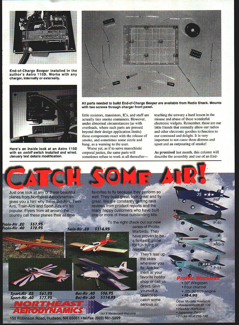
Components and construction
- The circuit can be built from Radio Shack parts; I revised the parts to use RS catalog items (which increased size slightly but not operation).
- Build on a small piece of perfboard or universal printed circuit holeboard.
- Mount the piezo beeper and wiring in a small plastic enclosure for external use. If installed inside a charger, observe polarity and make secure connections to the charger output leads.
Assembly drawing and board notes:
- The assembly drawing is a top (component-side) view. Printed circuit lands are underneath and shown as dotted lines on the drawing.
- Several lands are cut at marked X locations — do not forget this step.
- Observe all polarities and orientations (LM324 pinout, transistor orientation, etc.).
- Specific assembly clarifications:
- The zener diode cathode (black band) is "up" (toward the PC board top).
- IC1 pin 4 is wired on the top side of the board (under the IC) to the positive conductor.
- Q2 collector is wired to the beeper (+) terminal with a short jumper under the PC board (shown dotted on the drawing).
- Using an IC socket is recommended; insert the IC when all other soldering is finished.
Testing and operation checks
- Carefully examine the new circuit with a bench meter before powering up. Check component locations and solder joints.
- Test by connecting the beeper externally to a battery pack under charge and then shut off the charger manually. The alarm should sound following the applied voltage drop.
- If you have a variable-voltage power supply, power the circuit at a convenient voltage (5 V or more) and then quickly reduce the voltage or disconnect to trigger the alarm.
- The beep duration will be longer for larger pack voltages (C2’s decay time is voltage dependent). Loudness also varies with pack cell count up to a point.
Installation and mounting
- My beeper is mounted with two screws through the charger front panel using one-inch spacers (I used plastic ball-point pen bodies cut to length) between the circuit board and panel.
- If installing inside a charger:
- Locate the charger output leads and wire the two beeper power leads to the same points.
- Be very careful about polarity and don’t damage surrounding parts or wiring. Some chargers (e.g., the 110D) are tight inside — examine carefully with magnification before powering up.
- If unsure, have a skilled friend do the internal installation or use the EOC beeper externally.
- For external mounting you can use a small plastic box or encase the board in heat-shrink tubing. Heat-shrink covering in a variety of sizes is available from New Creations RC (Box 496, Willis TX 77378).
Final notes
- The EOC beeper has added to my electric flying pleasure; I hope it does the same for you.
- Please include a SASE with any correspondence for which you'd like a reply. If you wrote expecting a response and didn’t receive one, consider whether you forgot the SASE.
- Wishing everyone many happy, quiet electric landings!
Transcribed from original scans by AI. Minor OCR errors may remain.

