
RADIO CONTROL ELECTRICS
Bob Kopski 25 West End Drive, Lansdale PA 19446
This month's topics
- More on flight use of car motors
- Discussion of motor brushes
- Continuing discussion of motor battery charging from the auto battery
Car motors in flight use
Several recent columns included discussion of the discontinued Kyosho Mega motor and the newer Magnetic Mayhem replacement. I don't normally use car motors, but in this case I have found very nice performance when combined with a suitable gear drive, prop, and cell count. While the subject motors do have replaceable brushes, I still consider them "throwaways" because they have bushing bearings — not ball bearings.
I've been flying these quite a bit, and have proven the merit of the bearing comment: bushings wear all too soon. This is especially true of the front bearing, and when this happens the gear set is next in line to "go" because the now-sloppy bearing permits degradation of the mesh and subsequent rapid wear of the gears.
More than one modeler told me that it's a good idea to replace the bushings with ball bearings. They are right, and I've learned that the time to do this is when the motor is new. When I attempted to do this on a bearing-worn motor I was surprised to find that both the shaft and the front bearing were worn so that just replacing the bearing would be of little value.
I also found that while the front bearing was quite bad, the rear bearing showed little wear. I chose to re-bear a new motor (front bearing only) for starters; I'll probably wind up with both ball bearings.
Re-bearing a can motor (practical notes)
This sounds temptingly easy, but there's a catch. These motors are inexpensive, and the rear end bell is held in place with bent can tabs — no screws for easy disassembly. Undoing such tabs can be a real challenge.
A procedure that worked for me:
- Remove the brushes and scribe a reference mark on the can and rear end bell to assure accurate reassembly.
- Prepare a small chisel: grind a short piece of 1/8" music wire to a chisel point.
- With the motor nested in a V-block, use a hammer and the miniature chisel to cut through the tabs where they emerge from the motor can. If the homemade chisel is ground true and sharp, this is very easy.
- With the can tabs cut (and brushes removed), the rear end bell slips off easily and the armature can be pulled out.
- Rest the open end of the can on a flat, solid surface and push the front bushing out (from the outside inward). I used a short dowel that just fit the visible bushing perimeter, tapping it gently with a hammer.
- Fit a matching ball bearing (I found a 1/8" x 3/16" bearing — Dynamite part # DYN3106 — at my local hobby shop).
- With the motor housing front resting on wooden rail supports (allowing clearance for the exterior bearing "dimple"), gently tap the new bearing in place from the open rear end can using brass tubing that just fits the outer ring of the bearing (so as not to damage the race, balls, or inner sleeve).
- Reassemble the motor, positioning the rear end bell exactly as removed using the scribe marks. Hold it in place with a few drops of thin cyanoacrylate (CyA).
The new motor and a new Leisure drive were re-installed in the E-Motion from whence it came. I'm flying this combo quite a bit, and I'll report on how it holds up in a future column.
This is one very impressive power system per dollar, but it does not have the quality, stamina, and efficiency of the more costly Astro and Aveox products. I'm not suggesting that it's "as good as" those, but I am getting a lot of good airtime with it, and I know there is a need for more economical modeling supplies.
Brush wear and maintenance
Brushless motors are the only way I know to completely avoid brush-related problems. The most common form of brush trouble is simply brush wear — the sort of thing that creeps up on you. Many times I have neglected to do a timely visual check on my motor brush condition, only to pay a heavy price for this neglect.
As brushes wear, they naturally get shorter. Eventually they can get short enough that the embedded shunts — those short braided wires that emerge from the back of the brush blocks — come in contact with the commutator and ruin it. Replacing brushes before this happens is a whole lot cheaper. Minor commutator damage can probably be repaired by lathe-turning the commutator surface, if you have that resource. I don't, so every time I'm neglectful it costs me a new armature. This just happened with my fun-flyin' Model Electronics Turbo Plus 10; in the past I have done it to a few Astros.
I suggest inspecting brushes when a motor is new and replacing both brushes when either is worn by about one-third. Brushes usually wear unevenly in length, so use the shorter one as the guide. This is not a hard-and-fast rule but a practical guideline. Expect that smaller brushes usually wear more rapidly than larger ones under the same usage. For example, the brushes in car motors are smaller in cross-sectional area than those in Astro motors; for about the same average current, the smaller ones wear out more rapidly. For any motor, wear is more rapid the harder the motor is run (as motor current goes up).
Another aspect of brush wear may not be obvious: as brushes wear in length, the spring pressure pressing them to the commutator surface decreases. This can actually accelerate brush wear; as spring pressure decreases, the brush/commutator interface resistance increases, and local heating rises. This heating is quite detrimental to the brushes and speeds up the wear rate.
The first Astro Cobalts of the 1980s were breakthroughs at the time, but they were introduced with rather small brushes and light brush spring pressure. As time passed, Astro gradually improved the product to where the current versions have comparatively massive brushes and a lot more spring pressure. I remember discussions with Bob Boucher from the earlier days, and how field experience revealed these brush facts. Astro has steadily refined the product line over the years.
Be aware that brushes are made in different hardnesses:
- Soft brush material wears most quickly but is used in the highest-performance motors to get the best contact with the commutator (examples: Astro FAI versions).
- Hard brush material lasts longer but tends to have greater contact resistance (examples: low-cost Mabuchi can motors available under many trade names). These lower-cost can motors are often "throwaways" since servicing the brushes is not an easy option. Where servicing is an option, keep an eye on brush wear to avoid costly commutator damage.
Charging installation in the vehicle
Last month's column included some discussion and photos of the charging installation in my minivan. I detailed the installation under the hood at the auto battery. This month I cover details of the rest of the cable installation.
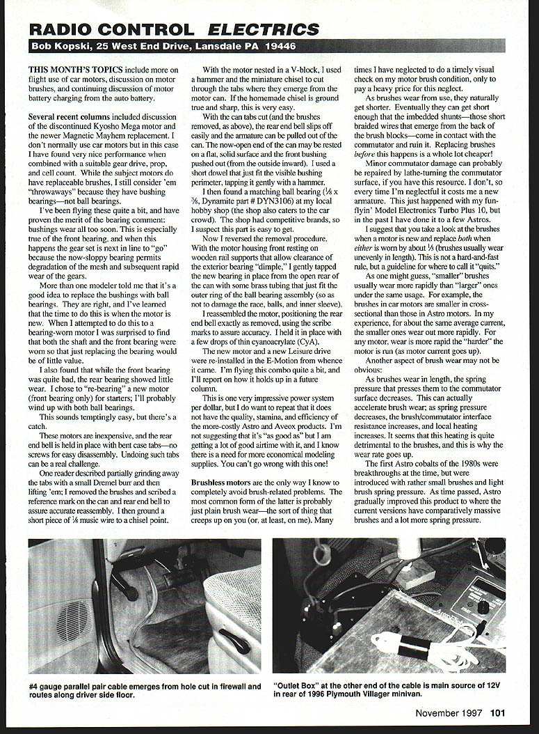
One cable pair emerges from under the dash and lays along the driver-side door sill. I had the dealer cut a hole in the firewall so that I could get the cable from the auto battery into the passenger compartment. The cable lays nicely along the floor, well out of the way of pedals and feet, and proceeds on back to the cargo area of the vehicle.
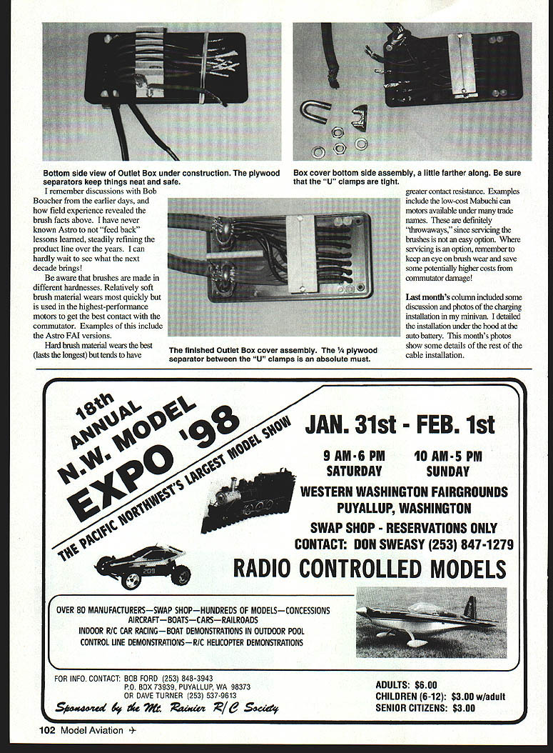
I chose to use Sermos connector sets for the outlet assembly. These were assembled as positive and negative pairs, with the pairs grouped in a row of seven and attached to the top cover plate of a plastic Radio Shack box. The seven pairs were individually interlocked and the resulting single seven-section "block" was held to the cover with the short plastic Sermos housings and through screws intended for such mounting purposes.
Inside the outlet box:
- I used 14-gauge high-flex wire installed in each Sermos contact, passing these wires through matching holes in the box cover.
- Each positive wire has a miniature 30-amp auto blade fuse soldered in it; each of the seven circuits is individually protected.
- The two wires and fuse from each connector pair are nested as a pair in individual sections of a grillwork made of 1/8" plywood to prevent circuit-to-circuit shorting and to afford neat wiring.
- A plywood cover plate, mounted on two standoff screws, holds everything captive within and between the wood separators.
- Large U-bolt clamps are used to connect and clamp each #4 conductor of the thru-car cable pair to its corresponding seven 14-gauge wires. Keep all negatives together and all positives together, and be absolutely certain of the cable polarity coming from the auto battery.
- Note the 1/4" plywood separator plate, which keeps the individual clamped conductor groups apart — an absolute must. This plate is held to the box cover plate with two sheet-metal screws. The heavy cable pair enters the box through notches cut in the plastic.
When the box bottom and top cover are assembled, all wiring and connector hardware are fully contained and safe. An 80-amp fuse was installed in the positive cable lead as a backup to the battery. In use, my chargers, a cooling fan, some convenience lighting, and a special interconnect cable to my household car battery charger are plugged into this Sermos connector box.
I routinely charge my car battery for an hour or so upon arriving home from a flying session. For me this is a short trip (less than 10 miles) and not enough to replenish the car battery. I have also installed an expanded-scale voltmeter and alternator current meter in my minivan so I can tell exactly when the alternator is recharging the battery.
New gear and closing
I just received some new FMA Direct S80 servos and they are tiny. I also got an FMA microreceiver and some other neat gear. This is all building up to a scaled-down mini-sized Revolt! Details later.
Please continue to enjoy Electrics right through the upcoming fall and winter seasons. Enclose a SASE with any mail for which you'd like a reply.
Transcribed from original scans by AI. Minor OCR errors may remain.

