
RADIO CONTROL ELECTRICS
Bob Kopski
25 West End Drive, Lansdale, PA 19446
This month's topics include a backward look at Ni-Cd batteries and some information on BEC operation and limitations.
Amazing—and very much appreciated—is the slow but steady growth in Ni-Cd battery technology over the last two-plus decades.
My first floundering electric flights occurred in 1972–73, when just about nothing for electric power was available at any hobby shop, including batteries. This was a time of "do-it-yourself" with a struggle. I remember struggling to rewind Radio Shack and other toy motors to make them somewhat more suitable for flight, and I recall the exasperation of trying to fit unwilling gears and a suitable prop to them. Then there was the small, light homemade super-regenerative receiver and the Adams actuator. I still see myself trying to power the whole works with an old receiver pack comprised of four button cells that had to be charged overnight in the classic manner (there was no such thing as high-rate charging then).
I remember that first powered “sink” half-circle of my original electric, ZAP 1—powered sink, and first-flight failure. ZAP 1 just didn't have the... But I kept at it, added a cell, changed the prop, and a few days later, success—one full shoulder-height circle immediately followed by a powered sink! ZAP 1 did fly, and I had successfully flown electric. This was absolutely exciting—mostly because it was an accomplishment from scratch. I had no references. There were no kits. There were no electric columns. Nothing. Boy, did that feel good!
From that first shoulder-height full circle until now, electric flight has been all "up" for me. Nowadays, a first successful electric flight for anyone is a given—a piece of cake. No challenge at all!
One of the keys to present-day electric ease has been the steady performance progress of Ni-Cd batteries. Those four button cells I mentioned were the thing in those days for powering radios, but not motors. The 450 mAh button cells were German-made, about 1 1/8 inches in diameter and maybe 1/4 inch thick. They had to be slow-charged, were not very forgiving of overcharge, and would only sustain a fairly light load. By today's standards, those cells were just plain lousy.
It took quite some time for much better cells to emerge. I recall eventually being able to buy better GE pencell-size Ni-Cds a few years later in the '70s. While these were better in many ways than the buttons, they still were not even close to today's products. They did allow me to advance to six- to eight-cell counts with rewound, geared slot-car motors operating at just under 40 watts. These power systems easily flew 15-ounce rudder-only glider-type airplanes—well past the ZAP 1 experience.
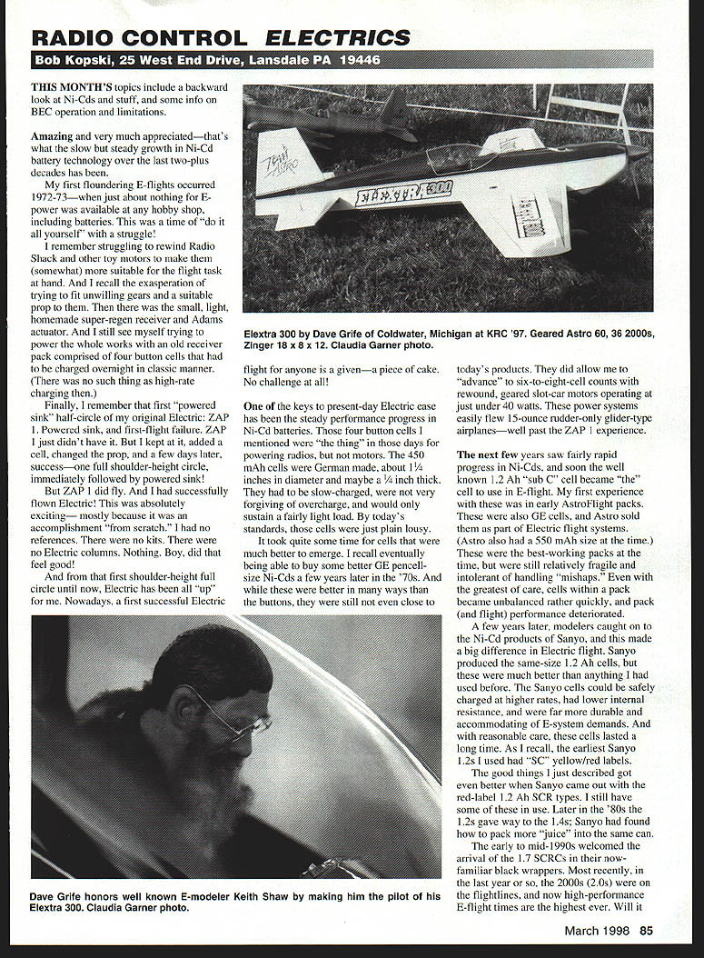
The next few years saw fairly rapid progress in Ni-Cds, and soon the well-known 1.2 Ah "sub-C" cell became the cell to use in electric flight. My first experience with these was in early AstroFlight packs. These were also GE cells, and Astro sold them as part of electric flight systems (Astro also had a 550 mAh size at the time). These were the best-working packs at the time, but were still relatively fragile and intolerant of handling mishaps. Even with the greatest of care, cells within a pack became unbalanced rather quickly, and pack and flight performance deteriorated.
A few years later, modelers caught on to the Ni-Cd products of Sanyo, and this made a big difference in electric flight. Sanyo produced the same-size 1.2 Ah cells, but these were much better than anything I had used before. The Sanyo cells could be safely charged at higher rates, had lower internal resistance, and were far more durable and accommodating of electric-system demands. With reasonable care, these cells lasted a long time. As I recall, the earliest Sanyo 1.2s I used had "SC" yellow/red labels.
The good things I just described got even better when Sanyo came out with the red-label 1.7 Ah SCR types. I still have some of these in use. Later in the '80s the 1.2s gave way to the 1.4s; Sanyo had found how to pack more "juice" into the same can.
The early to mid-1990s welcomed the arrival of the 1.7 Ah SCRCs in their now-familiar black wrappers. Most recently, in the last year or so, the 2000s (2.0 Ah) were on the flightlines, and now high-performance electric flight times are the highest ever. Will it ever stop? I hope the batteries make what electric flight has become.
It takes more than batteries to make what electric flight has become. All aspects of model power systems have progressed dramatically during these last two decades: motors, ESCs, and model designs. There is some hand-in-hand development here—if there were no market there would be no investment in product development; at the same time, these product developments fostered growth in electric-flight interest and participation, and hence more product development.
While I've focused on batteries, the heavy and growing demand for portable rechargeable power by the industrial and consumer market is a major reason batteries have progressed as much as they have. This, most of all, has permitted the level of electric flight we have today. Our present-day motors and electronics—as great as they are—just would not do the job with those button cells of two decades past.
BEC (Battery Eliminator Circuit)
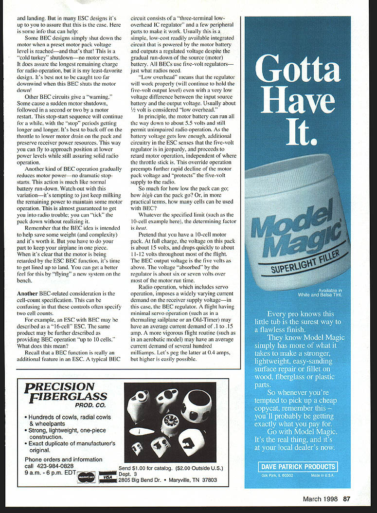
Electronic Speed Controls (ESCs) were among those advancements; one contemporary ESC feature that has become very popular is BEC (Battery Eliminator Circuit) operation. ESCs with a BEC option are particularly popular in the smallest electrics because the weight saving is most important there.
The BEC feature allows the speed control circuitry to also power the radio receiver and servos by diverting power to them from the motor battery. Thus no onboard radio battery (with its extra ounces) is needed.
For BEC to be practical, it must permit the radio to continue to function safely even as the motor battery gradually runs down. It should be obvious that a dead motor battery is automatically also a dead receiver battery; BEC circuitry monitors the motor pack voltage and retards motor operation before the pack gets too low. The radio can continue to operate—at least for a while. This "while" can vary quite a bit depending on many variables, but it should always be long enough to permit safe return and landing. In many ESC designs it's up to you to assure that this is the case. Here is some information that can help.
Types of BEC behavior
- Some BEC designs simply shut down the motor when a preset motor pack voltage level is reached—and that's that. This is a "cold turkey" shutdown with no motor restarts. It does assure the longest remaining charge for radio operation, but it's my least-favorite design. It's best not to be caught too far downwind when this BEC shuts the motor down.
- Other BEC circuits give a "warning." Some cause a sudden motor shutdown, followed in a second or two by a motor restart. This stop-start sequence will continue for a while, with the "stop" periods getting longer and longer. It's best to back off on the throttle to lower motor drain on the pack and preserve receiver power resources. This way you can fly to approach position at lower power levels while still assuring solid radio operation.
- Another kind of BEC operation gradually reduces motor power—no dramatic stop-starts. This action is much like normal battery run-down. Watch out with this variation—it's tempting to keep milking the remaining power to maintain some motor operation. This is almost guaranteed to get you into radio trouble; you can "tick" the pack down without realizing it.
Remember that the BEC idea is intended to help save some weight and complexity, and it's worth it. But you have to do your part to keep your airplane in one piece. When it's clear that the motor is being retarded by the ESC BEC function, it's time to get lined up to land. You can get a better feel for this by "flying" a new system on the bench.
Cell-count specification and heat considerations
Another BEC-related consideration is the cell-count specification. This can be confusing because ESCs often specify two cell counts.
For example, an ESC with BEC may be described as a "6-cell" ESC, and the same product may be further described as providing BEC operation "up to 10 cells." What does this mean?
Recall that the BEC function is an additional feature in an ESC. A typical BEC circuit consists of a three-terminal low-overhead IC regulator and a few peripheral parts. Usually this is a simple, low-cost integrated circuit that is powered by the motor battery and outputs a regulated voltage despite the gradual run-down of the source (motor) battery. All BECs use five-volt regulators—just what radios need.
"Low overhead" means the regulator will work properly (hold the five-volt output level) even with a very low voltage difference between the input source battery and the output voltage. Usually about 1/2 volt is considered low overhead. In principle, the motor battery can run all the way down to about 5.5 volts and still permit unimpaired radio operation. As the battery voltage gets low enough, additional circuitry in the ESC senses that the five-volt regulator is in jeopardy and proceeds to retard motor operation, independent of whether the throttle stick is full. This overdrive operation preempts further rapid decline of the motor pack voltage and protects the five-volt supply to the radio.
So much for how low the pack can go; how high can the pack go? Or, in more practical terms, how many cells can be used with BEC? Whatever the specified limit (such as the 10-cell example), the determining factor is heat.
Pretend you have a 10-cell motor pack. At full charge, the voltage on this pack is about 15 volts, and drops quickly to about 11–12 volts throughout most of the flight. The BEC output voltage is five volts. The voltage "absorbed" by the regulator is about six or seven volts over most of the motor run time.
Radio operation, which includes servo operation, imposes a widely varying current demand on the receiver supply voltage—in this case, the BEC regulator. A flight having minimal servo operation (such as in a thermaling sailplane or an Old-Timer) may have an average current demand of 0.1 to 0.15 amps. A more vigorous flight routine (such as in an aerobatic model) may have an average current demand of several hundred milliamps; 0.4 amps is easily possible and higher is not unusual.
Multiply the current demand by the voltage dropped across the regulator to obtain the power dissipation. For example:
- 6.5 V × 0.4 A = 2.6 W
- 7 V × 0.1 A = 0.7 W
- 7 V × 0.4 A = 2.8 W
These power numbers cause quite a bit of associated heat in the regulator. Properly designed ESC assemblies can safely accommodate this heat, but this gets harder and harder to do with increasing motor pack voltage. Most regulator ICs have internal self-protection features that shut down when the temperature gets too high; others simply burn up. The result is the same: no receiver power.
It should be clear why BEC regulators can only accommodate a limited range of motor pack cell counts. Exceeding the recommended cell count only serves to put BEC operation (and your airplane) in jeopardy. Remember, this is a totally independent matter from how many cells the speed-control function can handle for the motor.
One alternative is to use a switching-type regulator for the BEC. A switching regulator is much more efficient because it converts the excess voltage to pulses and stores energy in an inductor, so far less power is dissipated as heat. Switching BECs can handle higher input voltages (more cells) and higher output currents with much less thermal stress. They are, however, generally more expensive and may be a source of electrical noise if not properly designed.
Finally, remember that any BEC is sharing the motor pack as its source. If you push the motor pack hard (long, fast runs, hot motors), the pack voltage will be lower and the BEC has to work harder to maintain the five-volt rail. Keep an eye on your system in initial flights, and when in doubt, land early and check temperatures and connections.
The cell-count limit for BEC operation is not really a hardship. Generally speaking, BEC is most attractive in smaller, lighter airplanes, which usually have a low cell count anyway. Larger cell counts are generally associated with much higher motor operating power levels and larger airplanes; in that case, the burden of a separate receiver pack is not really a burden.
Modern BEC operation is very reliable and does serve a very good purpose in many flight applications. There was a time in my electric-modeling life when I would consider using BEC, but those times are past. Now I just need to keep in mind what's happening in that fast, high-flying airplane as the motor pack depletes, and resist the temptation to "thin" the motor run time.
I need self-control to maintain model control. I have to get the airplane lined up to land safely when the ESC/BEC warns me that the end is near—and so do you!
So ends one more E-column. Please enclose a SASE with any correspondence for which you'd like a reply.
Transcribed from original scans by AI. Minor OCR errors may remain.

