
RADIO CONTROL ELECTRICS
Bob Kopski, 25 West End Drive, Lansdale, PA 19446
THIS MONTH'S topics include information on a commercial version of the End-of-Charge Beeper, an End-of-Charge Beeper upgrade, and some comments on tiny E-R/C.
Lil Beep! — commercial End-of-Charge Beeper
The End-of-Charge Beeper (March 1997 column) was being considered as a potential product. (The EOCB is a simple device used in conjunction with your present motor battery charger to audibly signal when the charger has shut down.) I'm happy to announce the availability of a ready-built version. The product name is Lil Beep! and is available from New Creations R/C, Box 496, Willis, TX 77378; Tel.: (409) 856-4630. The price is $19.95.
The Lil Beep! is manufactured by John McCullough (of AULD fame) in Raleigh, NC. John has customized the printed circuit board so the device is somewhat smaller than the published version. I understand this ready-built version is already very popular—you may end up on a waiting list! I have no association with this business venture.
End-of-Charge Beeper upgrade — EOCBB
I've been trying to solve a problem associated with the popularity of the original End-of-Charge Beeper: some flight lines have so many EOCBs in use that modelers can't tell which beep is theirs. I have modified the basic design to allow some distinguishing sounds. The design changes permit you to easily modify any existing EOCB built according to the original drawings, or you can build this new version from scratch.
This version comes with a new name: the End-of-Charge Beeper-Beeper, or EOCBB. The EOCBB is only a little more complicated than the first version and affords four distinct sound options. You can choose yours during construction or even change the sound with a component change later on. In fact, one new sound option can be retrofitted into the original version with just one component value change; I'll describe this simple choice first. (It's best if you have the March '97 column at hand as we proceed.)
Resistor R5 and capacitor C5 function to sustain the beep sound for a short period (usually a few seconds). The actual time does vary somewhat with the cell count in the battery under charge — longer for more cells, up to a point. The beep duration you've become used to for the packs you normally charge can now be changed by changing R5.
- Original design value of R5: 33K (33,000 ohms).
- Change R5 to 100K to get a beep duration about three times longer.
- You can increase R5 up to about 220K for a nominal six-times tone length, although very long tones can be annoying.
- Experiment with intermediate values to suit your needs.
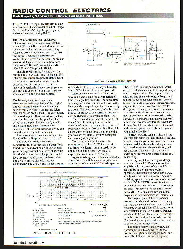
The EOCBB is actually a new circuit which comprises all the circuitry of the original design with some parts added. The additions change the original continuous beep to a pulsed beep—hence the new name. Experimentation suggests two audio options that are easy to distinguish: a faster pulsed beep and a slower pulsed beep. In either case, use a new R5 = 100K (or more) as shown on the drawings to allow plenty of time to hear the pulsed format.
You may recall the original design was based on the LM324 quad operational amplifier, with only two of the amplifier sections being used. The remaining two sections were simply wired in for convenience (it is bad design practice to allow an unused section to float). The EOCBB makes functional use of one of those previously unused op-amp sections, shown as IC1-2. A quick comparison of the original and new schematics will clarify this.
The original presentation showed an assembly drawing and a schematic that were each technically correct but did not agree with each other (this pseudo-error was discussed in the 7/97 column). Readers who built EOCBs to either drawing produced successful beepers. The new drawings presented here are believed to be correct and in agreement.
Functionally, the EOCBB operates like the original except for op-amp section IC1-2. IC1-2 is configured as a low-frequency square-wave oscillator that produces a several-cycles-per-second waveform. This waveform frequency can be varied with resistor R10; two values are recommended:
- R10 = 22K → approximately 12 cycles per second (faster pulsed beep)
- R10 = 47K → approximately 6 cycles per second (slower pulsed beep)
This low-frequency square wave is applied to the newly added transistor Q3, turning it on and off at the corresponding rate. Q3 is wired as an "and" gate with the original beeper control transistor Q2. Q2 works as before, but is now additionally gated by Q3 at the square-wave rate. This combination results in "beep-beep-beep..." sounds lasting for the R5-established duration.
Converting an existing EOCB to an EOCBB
Existing EOCBs can be converted by:
- Carefully removing the jumper wire on Q2 emitter and on IC1 pins 1, 2, 5, 6 and 7.
- Relocating R6 and replacing R5 (use the new R5 value you prefer).
- Installing all additional new wire jumpers in the locations shown on the drawings.
- Use short component lead cutoffs for shorter jumpers.
- Use insulated wire (Ace R/C wire, small-gauge speaker wire, or telephone cable wire) for longer jumpers.
- Stranded or solid wire is OK.
- Install Q3 and C3, then resistors R8–R13.
- Choose R10 per desired pulsed rate (you can change it later).
- Carefully check to assure none of the jumpers or component leads are touching; use a lens for inspection if desired.
You are then ready to check out the operation using the same procedures discussed in the 3/97 issue.
New builds — assembly suggestions
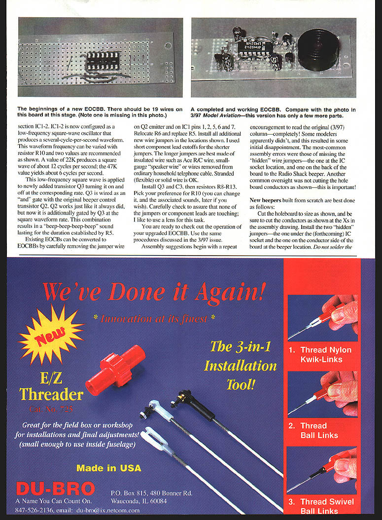
Begin by reading the original (3/97) column completely. The most common assembly errors were missing the "hidden" wire jumpers (one at the IC socket location and one on the back of the board to the Radio Shack beeper) and not cutting the holeboard conductors as shown — this is important!
Recommended build steps:
- Cut the holeboard to size as shown; be sure to cut the conductors at the Xs in the assembly drawing.
- Install the two "hidden" jumpers — the one under the forthcoming IC socket and the one on the conductor side of the board at the beeper location.
- Do not solder the jumper under the socket now — this will be done later when the socket is installed.
- Install the remaining jumper wires as shown.
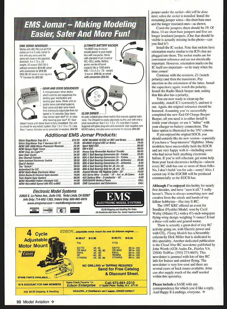
- Count the jumpers: there should be 19 total — 14 short bare jumpers and 5 longer insulated jumpers. (One jumper that should be visible is actually missing in the photo — can you find it?)
- Install the IC socket (note socket orientation marks are for convenience).
- Install resistors, Z1 (watch polarity), transistors (pay attention to orientation), capacitors (watch polarity), and the Radio Shack beeper (observe polarity).
- Clean up the assembly, solder the socket jumper, install IC1 correctly, and test.
Assuming successful completion, install the beeper inside your charger or use it inline with your charger-to-battery connections (the inline option is illustrated in the 7/97 column).
If you enjoyed the original EOCB, you should like the new EOCBB—especially on a "beep-intensive" flightline. Many modelers have successfully built the EOCB and are very happy with it, including some who had never built anything electronic before. If you're reluctant, get help from a local electronics hobbyist—almost every RC club has one or more. No, I don't build them for sale. Also, I cannot say if the EOCBB will be produced commercially like the EOCB has.
Tiny E-R/C
Although I've enjoyed this hobby for nearly five decades and have "seen it all," there is always something new and creative from the minds and hands of fellow hobbyists—like tiny E-R/C.
The 1997 NCRC offered an event for Smallest (Flyable) Model, won by Cecil Wheatly (Miami, FL) with a 4-1/2-inch wingspan flying-wing design weighing 1/2 ounce. It had a three-volt radio and geared motor.
There is a great deal of tiny R/C activity going on, with electric power and with CO2. Flying Models has a bimonthly column by Dick Miller dedicated to this specialty. Another dedicated publication is the Cloud Nine RC newsletter published by John Wertz (4326 Andes Dr., Fairfax, VA 22030; Tel/Fax: (703) 273-0607). This newsletter is jammed with tiny RC info for indoor and outdoor flying. The newsletter is low-cost and several years of back issues are available. John can also supply much of the specialty equipment needed.
Please include a SASE with any correspondence for which you'd like a reply.
And Happy E-Landings, everyone.
Transcribed from original scans by AI. Minor OCR errors may remain.

