


RADIO CONTROL ELECTRICS
Bob Kopski, 25 West End Drive, Lansdale PA 19446
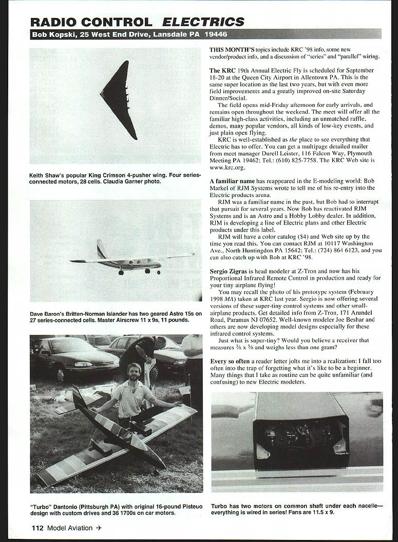
This month's topics include KRC '98 information, some new vendor/product news, and a discussion of "series" and "parallel" wiring.
KRC '98
The KRC 19th Annual Electric Fly is scheduled for September 18–20 at the Queen City Airport in Allentown, PA. This is the same excellent location as the last two years, with additional field improvements and a greatly improved on-site Saturday dinner/social.
- The field opens mid-Friday afternoon for early arrivals and remains open throughout the weekend.
- The meet will offer familiar high-class activities, including an unmatched raffle, demos, many popular vendors, low-key events, and open flying.
KRC is well established as the place to see everything electric has to offer. You can get a multipage detailed mailer from meet manager Durell Leister, 116 Falcon Way, Plymouth Meeting, PA 19462; Tel.: (610) 825-7758. The KRC website is www.krc.org.
RJM Systems (Bob Markel)
A familiar name has reappeared in the electric modeling world: Bob Markel of RJM Systems wrote to announce his re-entry into electric products.
RJM was well known in the past, but Bob had to interrupt that pursuit for several years. Now he has reactivated RJM Systems and is an Astro and Hobby Lobby dealer. RJM is also developing a line of electric plans and other electric products under this label.
RJM will have a color catalog ($4) and a website up by the time you read this. Contact RJM at 10117 Washington Ave., North Huntingdon, PA 15642; Tel.: (724) 864-6123. You can also catch up with Bob at KRC '98.
Z-Tron Proportional Infrared Remote Control
Sergio Zigras, head modeler at Z-Tron, now has his Proportional Infrared Remote Control in production and ready for tiny airplane flying. You may recall the photo of his prototype system (February 1998 MA) taken at KRC last year. Sergio is now offering several versions of these very small control systems and other small-airplane products.
Get detailed info from Z-Tron, 171 Arundel Road, Paramus, NJ 07652. Well-known modeler Joe Beshar and others are developing model designs especially for these infrared control systems.
Just how small? Consider a receiver that measures 3/8" x 5/8" and weighs less than one gram.
Series and Parallel Wiring
Every so often a reader letter jolts me into a realization: I fall too often into the trap of forgetting what it's like to be a beginner. Many things that seem routine to me can be unfamiliar and confusing to newcomers. The terms "series" and "parallel," while ordinary to experienced modelers, often stump those new to electric flight. Multimotor installations provide a useful way to illustrate the differences.
- A cell is generally considered to be an individual electrochemical assembly.
- A battery is an interconnection of cells.
Consider the familiar two-cell flashlight. This flashlight normally has four electrical components:
- two cells (making up one battery),
- a light bulb,
- a switch.
These four components are connected end-to-end (i.e., in series). If one disregards the switch and views the two cells as a single battery, the same flashlight can be viewed as a parallel connection of the bulb across the battery. As you can see, series and parallel may be a matter of point of view.
Key principles:
- Cells connected in series form a battery whose total (terminal) voltage is the sum of all the cells' voltages. For example, two 1.5 V cells in series give about 3 V total.
- In any series connection, the same current flows through all components in the path.
- In a parallel connection, each component sees the same source voltage, while the total current is the sum of the currents drawn by each component.
Examples:
- A pure series connection: old-fashioned Christmas light strings—if one bulb opens, the whole string goes out.
- Household wiring: everything plugs into the 120 V AC mains and is wired in parallel; turning one appliance on or off does not affect others.
- Car electrical system: every accessory is connected across the car battery (parallel), while the battery itself is made of six 2 V cells in series.
Voltage drops in series: if a 120 V outlet feeds a string of 35 identical bulbs, each bulb drops approximately 120 / 35 ≈ 3.4 V. From the outlet's point of view, the string is a single load, in parallel with other household appliances. But within the string, voltages add and the same current flows through all bulbs.
Application to Aeromodeling: Multimotor Installations
Conceptually, the simplest power system is a battery and a motor. In practice, it includes wiring, a switch, a fuse, an ESC (Electronic Speed Control), connectors, etc. You can view the motor and battery as being in parallel when the system is on, or you can view the installation as a series connection of the motor, the cells in the battery, and the other components. For twins and quads, wiring choices matter.
Twin wiring options:
- Series wiring:
- Connect negative of motor one to the battery negative, positive of motor one to negative of motor two, and positive of motor two to the battery positive.
- The single battery must be of twice the voltage (twice the cell count) required by a single motor, because the identical motors divide the available voltage.
- The same current flows through each motor and through each cell in the battery.
- Parallel wiring:
- Connect positive of motor one to positive of motor two, and negative of motor one to negative of motor two, then connect to the battery.
- Each motor sees the same source voltage and operates at its normal current, but the battery must supply the sum of the motors' currents (twice the current of one motor for a twin).
Which should you use?
- Generally, most twin installations should use series connections. Doubling the current (as in parallel wiring) increases installation losses rapidly and is harder on wiring, switches, connectors, and speed controls. Losses typically increase at least quadratically with current.
- Exceptions exist. For example, Speed 400-class motors operate at about 10 A max. Doubling to 20 A with two motors in parallel results in a system current comparable to many single-motor systems, so parallel or series can both be acceptable.
- Practical considerations such as charger limitations, cost of increasing cell count, or available ESC ratings may drive the decision. There may be more than one acceptable way—choose what makes sense for the overall system.
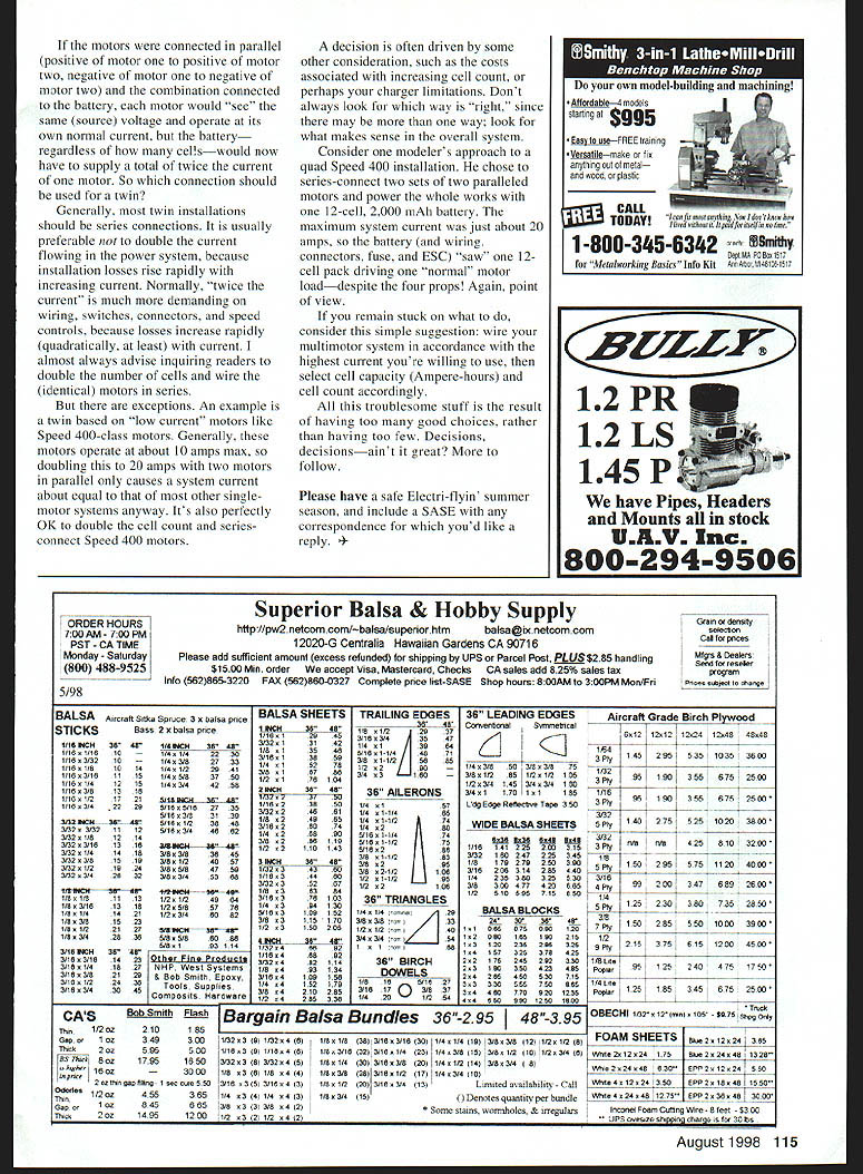
Example: one modeler series-connected two sets of two paralleled Speed 400 motors and powered the whole setup with a single 12-cell, 2000 mAh battery. The maximum system current was about 12 A, so the battery and associated hardware "saw" one 12-cell pack driving one normal motor load, despite four props—again, a matter of point of view.
If you remain uncertain, a simple suggestion: wire your multimotor system according to the highest current you're willing to use, then select cell count and battery capacity (ampere-hours) accordingly.
All this choice is a result of having many good options rather than too few. Decisions—ain't it great? More to follow.
Please have a safe Electri-flyin' summer season, and include a SASE with any correspondence for which you'd like a reply.
Transcribed from original scans by AI. Minor OCR errors may remain.

