
Radio Control: Electrics
Author
Bob Kopski 25 West End Dr., Lansdale PA 19446
Introduction
This month’s column shares new findings on the Sport Speed Control (SSC), follows up on recent product info, offers a circuit assembly aid, and continues the ongoing discussion for aeromodelers who would like to try electric power.
This issue includes the final installment of the two-part Sport Speed Control article — a build-it-yourself project for E-modelers who have some electronic assembly experience.
Developed over several years, the SSC is offered as a many-featured, but robust, design. Evidence supporting the latter is in data I’ve taken on SSC temperature behavior.
SSC in Aerobatic Service
Perhaps the harshest application among my numerous SSCs is in an aerobatic Senior Skybolt (see 2/99 column), where I have a 12-cell .15 geared installation, plus three midsize servos using the SSC BEC (Battery Eliminator Circuit) option.
I’ve described the SSC for use up to 16 cells, but up to 12 cells when the BEC is used. BEC operation with "more cells" and with larger and/or more numerous active servos is a heating-intensive combination for the regulator device with any speed control. In the SSC, the aluminum plate is the common heat collector for all of the motor-control semiconductors and the BEC regulator; it’s the collective heat equalizer for the speed control.
While I’ve known for a long time by simple touch that the SSC was working well in the above application, I got curious about the detailed thermal behavior. I attached an LM34DZ temperature sensor to the middle heat-sink location of the SSC, and read the temperature before and after eight flights spread over several days.
The average temperature rise above ambient was 49.8°F. If the temperature was 90°F on the field, the SSC plate would rise to about 140°F at the end of the flight. Typical flights were more than eight minutes.
This outcome is very good. I’m comfortable with this limited temperature increase during such a BEC-driven and fairly long aerobatic exposure, during which time the throttle and all servos were well-exercised.
This SSC installation is not in an optimum location; it is low on the floor, behind the elevated motor mount plate, and underneath the airstream passing the motor to the motor pack.
Expanded Testing and Results
In another experiment, prompted by an inquiry from someone who has already built the SSC, I installed an SSC in a REVOLT with a direct-drive .40 on 18 cells. This clearly exceeds the earlier-stated 16-cell limit. This SSC installation has operated very well, with 16 flights to date. It seems my original 16-cell limit was a bit conservative.
I also subjected an SSC to a bench exercise using a high-current power supply set to 22 volts, and a .40 direct-drive to a 10x6 on a test stand. I used the same temperature sensor technique as above, without BEC, and wrapped the SSC in one inch of foam to maximize (make as bad as possible, on purpose) the temperature environment (not recommended for flight).
I ran up the motor in slow steps during a 16-minute period. By the time I reached a motor input condition of 18 volts and 27 amps (the motor was very hot), the SSC baseplate temperature was 122°F in a shop ambient of 74°F. This is just fine.
The SSC performs thermally with good margin in 12-cell, BEC-powered aerobatic applications, and so far in an 18-cell, .40-size application without BEC.
As time goes on, I’ll look more carefully at expanding the SSC limits of operation. For now, the first-stated application range recommendation of six to 16 cells is adjusted to six to 18 cells, based on the info above, and excellent, safe operation with BEC up to 12 cells is reaffirmed by hard data for SSCs built as described in the article.
For those astute readers who have followed the SSC article and the column: yes, the 18-cell test operates the SSC just past the adjustment range for the motor cutoff circuit operation. The maximum range of R52 puts the cutoff value at about 0.87 volts per cell for 18 cells instead of my preferred 9-volt number.
This is not a major matter, since the original choice is somewhat arbitrary. Nevertheless, I’ll address this issue in the future.
Parts and Tools — Pricing Follow-up
Recent columns have included references to Tech America, a Tandy company parts supplier, and a DMM (Digital Multi‑Meter) from Radio Shack.
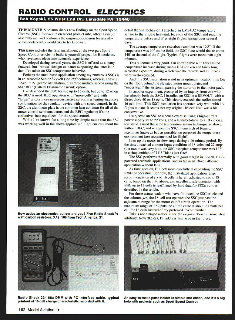
One photo showed two packets of 1/4-watt 5% carbon resistors, such as those used in the SSC article. The five-resistor packet costs 49¢ at Radio Shack (also a Tandy company), and the 100-piece resistor packet from Tech America costs $1. Both are regular (not sale) prices, and both are single-value packets.
Active circuit builders will surely appreciate the price difference. I offer this in support of my earlier claim that Tech America does offer very good pricing on some items.
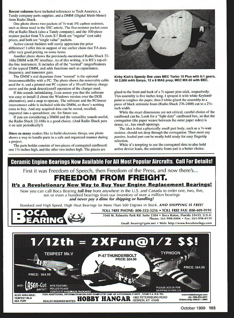
Another photo shows the previously mentioned Radio Shack 22-168a DMM with PC interface. As of this writing, it is RS’s top-of-the-line instrument. It includes all of the normal ranges/features of a typical DMM, and adds functions such as capacitance, frequency, and transistor gain.
The DMM’s real departure from normal is the optional interconnectivity with a PC. The photo shows the removable cable used for it, and a printed-out PC capture of a 10-cell battery charge curve and the peak detect/cutoff operation of the charger used.
If this sounds intimidating, I can assure you that the software was easy to install (I chose the Windows version over the DOS alternative), and a snap to operate. The software and the PC/meter interconnect cable are included with the DMM, so there’s nothing extra to buy. Any acquired data can be stored, recalled, imported into a spreadsheet, etc. for future use.
If you are considering a DMM and the versatility sounds useful, the Radio Shack 22-168a is a good choice. (And Radio Shack puts it on sale periodically.)
Circuit Assembly Aid — Parts Holder
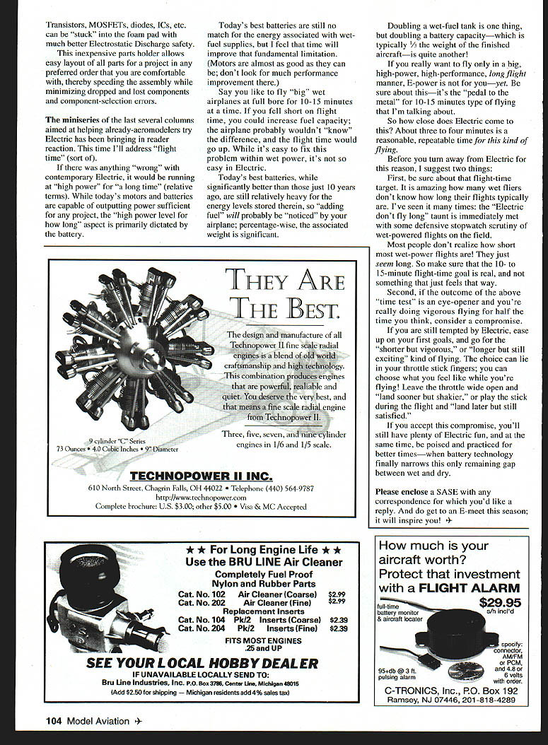
Since so many readers like to build electronic things, one photo shows a way to handle parts in a safe and organized manner during a project.
The parts holder consists of two pieces of corrugated cardboard: one 1-1/4 inches high, and the other two inches high. The pieces are glued to the front and back of a 3/4-inch square pine stick, respectively. This assembly is five inches long. I sprayed it with white Krylon paint to toughen the paper, then glued the assembly to a piece of black antistatic foam (Radio Shack 276-2400) cut to a 2-1/4-inch width.
While the exact dimensions are not critical, careful choice of the cardboard can be made. Look for a light-duty cardboard box, so that the corrugation (the paper weave between the outer paper sides) is dense, i.e., has small openings. The idea is that a physically small part body, such as a 1/4-watt resistor, should not drop through the corrugation. Then most any passive, leaded part can be neatly held ready for easy fingertip selection.
While it’s tempting to use the corrugated slots to also hold active device leads, the antistatic foam pad is a better choice. Transistors, MOSFETs, diodes, ICs, etc. can be stuck into the foam pad with much better electrostatic discharge safety.
This inexpensive parts holder allows easy layout of all parts for a project in any preferred order, thereby speeding assembly while minimizing dropped and lost components and component-selection errors.
Electric Flight Time Discussion
The miniseries of the last several columns aimed at helping already-aeromodelers try electric has been bringing in reader reaction. This time I'll address flight time (sort of).
If there was anything "wrong" with contemporary electric, it would be running at high power for a long time (relative terms). While today's motors and batteries are capable of outputting power sufficient for any project, the "high power level for how long" aspect is primarily dictated by the battery.
Today's best batteries are still no match for the energy associated with wet-fuel supplies, but I feel that time will improve that fundamental limitation. (Motors are almost as good as they can be; don't look for much performance improvement there.)
Say you like to fly big warplanes at full bore for 10–15 minutes at a time. If you fell short on flight time, you could increase fuel capacity; the airplane probably wouldn't "know" the difference, and the flight time would go up. While it's easy to fix this problem within wet power, it's not so easy in electric.
Today's best batteries, while significantly better than those just 10 years ago, are still relatively heavy for the energy stored therein, so "adding fuel" will probably be noticed by your airplane; percentage-wise, the associated weight is significant.
Doubling a wet-fuel tank is one thing, but doubling a battery capacity — which is typically the weight of the finished aircraft — is quite another.
If you really want to fly only in a big, high-power, high-performance, long-flight manner, electric power is not for you — yet. Be sure about this — it's the "pedal to the metal" for 10–15 minutes type of flying that I'm talking about.
So how close does electric come to this? About three to four minutes is a reasonable, repeatable time for this kind of flying.
Before you turn away from electric for this reason, I suggest two things:
- Be sure about that flight-time target. It is amazing how many wet fliers don't know how long their flights typically are. I've seen it many times: the "Electric don't fly long" taunt is immediately met with some defensive eyewitness recounting of wet-powered flights on the field. Most people don't realize how short most wet-powered flights are — they just seem long. So make sure that the 10- to 15-minute flight-time goal is real, and not something that just feels that way.
- If the outcome of the above "time test" is an eye-opener and you're really doing vigorous flying for half the time you think, consider a compromise. If you are still tempted by electric, ease up on your first goals, and go for the "shorter but vigorous" or "longer but still exciting" kind of flying. The choice can lie in your throttle-stick fingers; you can choose what you feel like while you're flying. Leave the throttle wide open and land sooner but shakier, or play the stick during the flight and land later but still satisfied.
If you accept this compromise, you'll still have plenty of electric fun, and at the same time be poised and practiced for better times — when battery technology finally narrows this remaining gap between wet and dry.
Closing
Please enclose a SASE with any correspondence for which you'd like a reply. And do get on E‑meet this season; it will inspire you!
Transcribed from original scans by AI. Minor OCR errors may remain.

