
Radio Control: Electrics
Bob Kopski
More electric activity
The Daniel Boone Silent Fliers' annual 2‑Meter RC Soaring contest was held Saturday–Sunday, September 28–29, 1985, at the Daniel Boone Homestead near Pottstown, PA. This year there was more than 2‑Meter Soaring going on—there was Electric activity as well. CD Jerry Zeigenfuse explained that interest in Electric among soaring enthusiasts is growing, partly because it avoids the unpleasantness of hauling winch systems. A trial Electric event was included in the 1985 meet.
Format
- Five flights per competitor.
- Maximum flight time: 8 minutes.
- Any motor run up to 3 minutes was allowed.
- Flight timing began at motor shutdown; no motor restart allowed.
- Motor runs over 3 minutes resulted in a zero score for that flight.
- Maximum score: 60 × 8 = 480 points per flight; all flight scores were added for a total.
- One minute allowed to get the plane down after a max. No spot‑landing task was used.
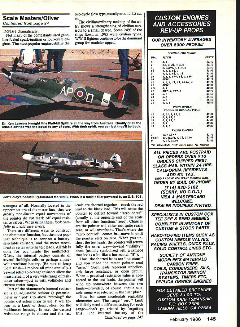
Saturday saw eight participants flying in a very strong wind (a hurricane had passed up the East Coast the day before). Sunday was a beautiful day with another eight participants. I attended Saturday only and understand the flying on Sunday was much better.
Top three finishers
Saturday
- 1. Skip Schow — 2,139 points
- 2. Bill Meleske — 2,114 points
- 3. Woody Blanchard — 1,866 points
Sunday
- 1. Bill Meleske — 2,400 points
- 2. Ken Stinson — 2,400 points
- 3. Skip Schow — 2,059 points
Notes
- Several of these pilots had flown at the KRC Electric Fly the week before and did very well there, too. LSF Level Five Bill Meleske took Up‑Last‑Down at the KRC meet with the same plane.
- At KRC, Bill battled Ken Stinson’s Spectra; both maxed five times and went to a flyoff. That was Ken’s first contest ever.
- Hats off to the Daniel Boone Silent Fliers for a fine first‑ever Electric meet. Early indications are they’ll do it again in 1986.
If your club has an upcoming meet, add a simple Electric event. Keep it simple and start small—size doesn’t matter. Give me the details at least three months in advance and I’ll announce it here. A major chunk of modeldom’s future belongs to Electric—start making the future happen.
Motor electrical noise
Last month’s column mentioned the common sound of motor power interruptions caused by radio glitches. At the 1985 KRC Electric Fly it was clear that on‑board electric power systems can cause radio static quite easily—almost like a built‑in on‑board glitch maker. There are several ways to reduce or eliminate the problem.
- Use an optically‑coupled electronic speed control
- Optically coupled means the receiver‑associated circuitry is electrically isolated from the speed‑control circuitry that is connected to the motor. The control signals decoded by the receiver drive light‑generating and light‑detecting components; the power control side is isolated from the receiver electrically.
- Speed controls that are not optically coupled have a solid electrical connection between the receiver and the motor/power system—this conducts brush noise right into the radio system. That makes it harder for the receiver to reject motor noise and can cause glitches and range reduction.
- I prefer to use only optically isolated speed controls.
If you use a servo‑activated switch instead of an electronic speed control, there may already be adequate isolation. Servo output arms and wheels are normally nonconductive plastic, which helps provide separation.
- Keep wiring neat and separated
- Route the radio wiring and motor/power wiring apart where possible. Motor wiring acts like a small transmitting antenna; close proximity to the receiver and its wiring degrades the effective communications link.
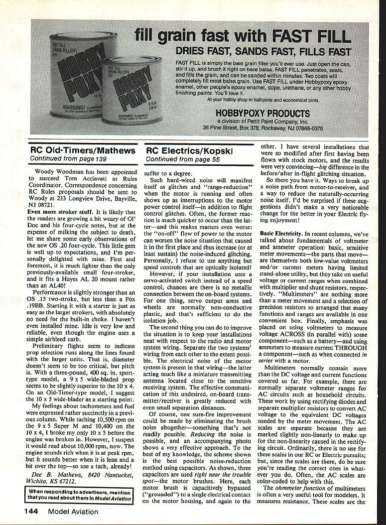
- Reduce the motor noise at the source with capacitors
- A very effective scheme is to place three capacitors right at the motor brushes. Each brush is capacitively bypassed to the motor housing (ground), and one capacitor is placed between the two brush lugs. This arrangement greatly reduces brush noise radiated by the motor.
- Typical values: ceramic capacitors of 0.001 µF and 0.01 µF work well. Use parts with a 50‑volt rating if possible.
- On some installations a diode near the center capacitor is used to protect an electronic speed control from back EMF.
- I’ve modified several stock motors this way and seen a convincing reduction in in‑flight glitching.
Other notes
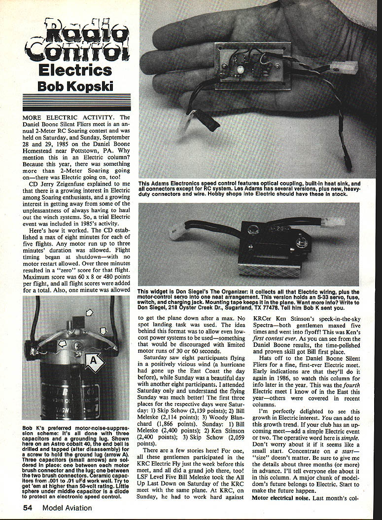
- Some manufacturers (and hobby shops) offer speed controls with optical coupling, built‑in heat sinks, and heavy‑duty connectors. These are worth seeking out.
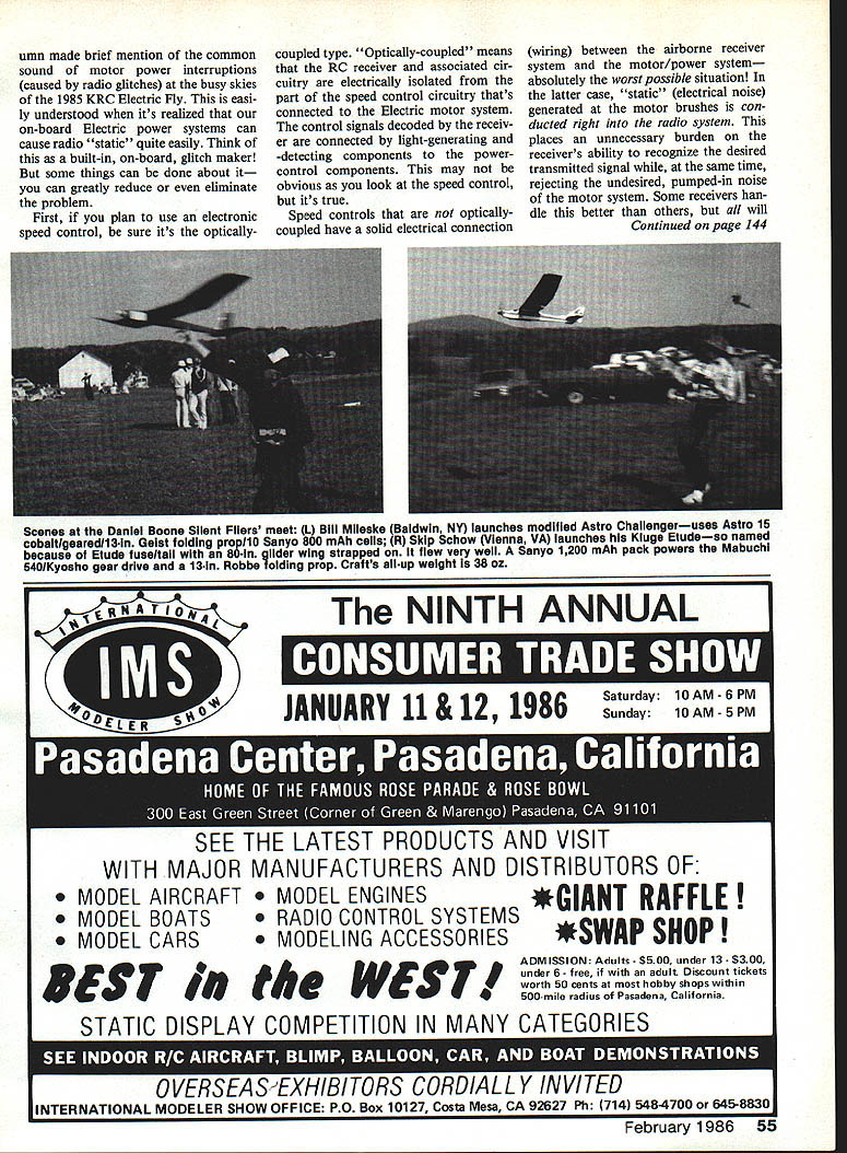
- Don Siegel produces an organizer that collects electric wiring and motor‑control servo wiring into a neat package (holds an S‑33 servo, fuse, switch and charging jack). Mounting tape secures it in the plane. For information, write Don Siegel, 218 Oyster Creek Dr., Sugarland, TX 77478 (tell him Bob K sent you).
Basic Electricity
Recent columns covered fundamentals of voltmeter and ammeter operation. Sensitive meter movements are low‑value voltmeters or current meters; they become useful voltage or current meters when combined with multiplier and shunt resistors. Multimeters are essentially a meter movement and a selection of precision resistors arranged to provide many functions and ranges in one instrument.
- Use voltmeters to measure voltage ACROSS (in parallel with) a component, such as a battery.
- Use ammeters to measure current THROUGH a component, by connecting the meter in series.
Multimeter AC voltage ranges
- Multimeters usually include AC voltage ranges. These ranges work by rectifying the AC and filtering it, then scaling the resulting DC to drive the meter movement. Because the rectifier circuit is nonlinear, AC scales are made slightly non‑linear and are usually marked or color‑coded—be sure you’re reading the correct scale.
Ohmmeter function
- The ohmmeter measures resistance by applying a small internal voltage and reading the resulting current. This test signal is normally harmless in power‑system use but can affect sensitive solid‑state circuits. Never connect an ohmmeter to an active circuit (battery or running motor); the meter is for measuring unpowered circuits only—failure to heed this may damage the instrument.
Examples of useful checks with a multimeter/ohmmeter
- Check optical isolation
- With both receiver and motor switches OFF, select the highest resistance range and zero the instrument. Connect one ohmmeter lead to a receiver electrical point (battery terminal, unused servo plug contact, or exposed charge plug contact) and the other lead to a motor circuit point (brush connection or motor battery terminal). An optically‑isolated system should read as “infinite” resistance—no movement on the meter. Non‑isolated controls will show a measurable resistance.
- Measure motor resistance
- Select a low resistance range and zero the meter. Disconnect the motor from any system connector and connect the test leads to the motor terminals. You should see a very low ohms reading, which will vary slightly as you turn the armature because of brush contact and commutator segment variations. Very large swings or obviously high resistance can indicate poor brush contact or a bad commutator segment.
- Generate voltage with a spinning motor
- With a low voltage DC range selected, spin the motor armature by hand. The meter pointer should move several volts. Reversing the meter leads will reverse the pointer deflection. A DC permanent‑magnet motor also functions as a generator when driven.
Other practical observations
- Most multimeter resistance ranges are of limited value in Electrics where you generally need only “open” or “short” (continuity) information. The mid‑range resistances are more useful when working on receivers, transmitters and other electronic assemblies.
- A simple household example: measure the resistance of a light bulb (unscrewed) by touching the meter leads to the base contacts. Values range from a few ohms for a 100 W lamp to a few hundred ohms for small night‑light bulbs.
- A quick “fun” demo: on the highest ohms range hold the meter leads in your fingers and note the resistance. Squeeze or moisten your hands and observe the resistance change—your body is a measurable conductor.
That’s it for this issue. Here’s wishing you many happy, quiet winter landings—Electrics are great in cold weather when glow fuel gets gooey and smelly.
Please forward questions and comments (with SASE) to: Bob Kopski 25 West End Dr. Lansdale, PA 19446
Transcribed from original scans by AI. Minor OCR errors may remain.

