
Radio Control: Electrics
Bob Kopski
FLASH! I've just received a letter from a friend and fellow electric flier, Joe Beshar. Joe is the hardworking chairman of the Team Selection Committee for the 1986 World Championship F3E Electric Glider competition to be held in Lommel, Belgium on August 22–30, 1986, and he wants to spread the word about this opportunity.
I personally know several very competent fliers who could do a top-notch job representing the U.S.A. in this world meet, and I encourage all interested to read on. Team qualification must be made by March 31, 1986, and candidates will participate in Team Selection Finals to be completed by June 30, 1986. For more details, please refer to the July 1985 issue of Model Aviation (page 109), write AMA HQ, or call Joe at (201) 768-5500. Joe is very spirited and enthusiastic and has been working long and hard to position the U.S. for these World Championships. This is your chance to "go for the gold!"
A survey — the KRC Electric Fly
The January 1986 column provided coverage of the 1985 KRC Electric Fly, and I want to thank Model Aviation for allowing me some extra photos beyond the normal column format. We at KRC attempt each year to survey those in attendance and collect info on the planes they are flying. Each year, with increasing attendance, this task gets bigger and has reached the level where it appears impossible to gather info on every plane. We were able, however, to get details on many modelers and planes last September, and I thought I'd share some of the tally with you.
In looking over the variety of information collected, I took particular note of what power systems were used in the very large electric array present. Here's what the attendees from 23 states and Canada reported for motors:
Motor tally (attendees from 23 states and Canada)
- Astro 02 — 2
- Astro 035 — 2
- Astro 035 (belt) — 4
- Astro 05 — 2
- Astro 05 XL — 1
- Astro 075 XL — 1
- Astro 05 cobalt — 18
- Astro 05 cobalt (geared) — 10
- Astro 15 cobalt — 4
- Astro 15 cobalt (geared) — 10
- Astro 15 SF — 1
- Astro 25 cobalt — 1
- Astro 25 cobalt (geared) — 1
- Astro 40 cobalt — 2
- Graupner 540 & 550 — 3
- Keller 25/123 — 3
- Keller 50/241 — 1
- Leisure LT 50 (direct) — 2
- Leisure LT 50 (geared) — 11
- Robbe 50 GSE — 2
- Robbe 30G — 1
- Others — 5
From this tabulation, it should be clear what is popular among electric modelers. Although this survey was taken at only one meet and is incomplete, it's obvious that the smaller cobalts, geared and not, find favor. This is no doubt due to their relatively small size and weight and their relatively high power-handling ability—despite their comparatively higher cost. Also, the smaller, easy-to-charge batteries used with these motors add to their appeal.
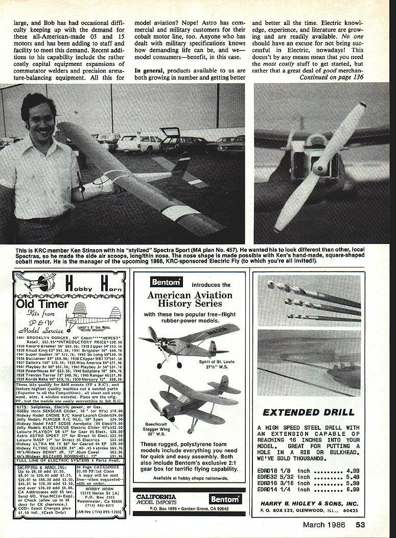
Bob Ellis' "Grumman's Grandma," a magnificently constructed Fleet biplane, used a belt-drive Astro 15 cobalt turning a 13x8 prop. Battery: 12 cells, 2,012 mAh capacity. A removable battery tray with bullet contacts fits several planes. Also shown was a light carrying case used to transport several built-up battery packs.
Astro Flight has had occasional difficulty keeping up with demand for these all‑American‑made .05 and .15 motors and has been adding staff and facility to meet demand. Recent additions include rather costly capital equipment expansions such as commutator welders and precision armature-balancing equipment. Astro also has commercial and military customers for their cobalt motor line, so model consumers benefit from the higher production standards demanded by those markets.
In general, products available to us are both growing in number and getting better all the time. Electric knowledge, experience, and literature are growing and are readily available. No one should have an excuse for not being successful in electric flight nowadays. This doesn't mean you need the most costly gear to get started, but rather that a great deal of good merchandise is available.
There is one thing I do find curious in the previous tabulation. While I do understand the price appeal of smaller motors, larger ones are not that much more expensive, and I have a hard time understanding why .25s and .40s don't find more acceptance. Personally, I fly all sizes and find the larger planes appealing in their ground-handling ability. I do appreciate the extra demands they place on charging, but there are ways to deal with charging larger packs (see Model Aviation, May and June 1985), and you may want to consider all these aspects as you plan your next electric project.
Electric Aeromodelling Association (EAA)
There have been some turbulent times for the specialist organizations dedicated to the electric cause. SEAM (The Society of Electric Aircraft Modelers) disappeared sometime during the past year and, so far as I know, is a dead issue. This is unfortunate because SEAM was the original, AMA‑recognized specialist organization for electric interests.
One surviving organization, the Electric Aeromodelling Association (EAA), continues to provide a focus for electric modelers and to publish a newsletter. If you're interested in joining or learning more, contact the EAA for current membership information and publications. The EAA, which looked shaky for a while (my annual dues check was returned from a "nobody here" box number), now appears to have an organized foothold. Two organizations for such a small interest group was unnecessary; I'm feeling better now with one, and I personally wish the EAA well.
Electric needs a unified representative voice for what promises to be explosive growth in the next decade. In this regard, I encourage you to write to EAA at P.O. Box 39, Midway City, CA 92655 and request membership information. Annual dues are $10 (less than a gallon of glow fuel), and you get a quarterly newsletter (The Silent Fly Sheet) dedicated to electric interests. EAA president is Bob Stiff, a well-known electric modeler and "Watts Up" columnist for Model Airplane News. Bob runs Hobby Horn in California and manufactures kits for some electric suppliers.
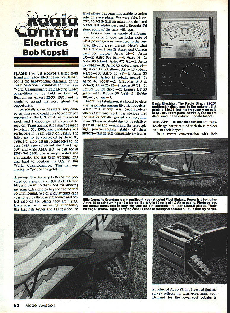
Basic Electricity — multimeter tips
By now, you should have a pretty good idea of how that handy gadget—the multimeter—works and how to use it at a basic level. In recent installments of this mini‑series we've seen the ideas behind the voltmeter, ammeter, and ohmmeter functions of a standard analog multimeter (the kind with a moving pointer). Before we move to the digital multimeter, there are a few more sidelights about the analog type that may be of interest.
Generally, multimeters include accessory or utility features such as extra test-lead jacks or special switches. For example, the Radio Shack instrument pictured has four test-lead jacks, and so far we've only detailed the use of two—the "normal" ones. For that example, the jack marked "-COM" or "negative common" is always used; connect the black test lead there. The jack to the right is marked "+V A Ω" (positive Volts-Ohms-Amps) and is where the red test lead goes. These are the connections used for just about all purposes. Almost all function switch positions operate with the test leads in these connectors.
One of the remaining jacks is marked "+DC 1000V" and is self-explanatory. With the black lead in "-COM" and the red lead in this connector and the function switch set to the 250/1000 positions in the DCV sector, you're all set to check out that new 833‑cell battery!
With the black lead in "-COM" and the red lead in the "+10A" or "positive DC 10‑amp" connector, and the function switch set to "10A" in the DCA sector, you're ready to measure smaller motor currents or the charging current for your motor battery. Remember to connect ammeters in SERIES with the circuit under test!
These two special jacks are separate from the two normal jacks because the function switch, which selects the multipliers and shunts for other ranges, cannot safely handle either the very high voltage or very high current applied via these connectors. While the switch selects the proper function and scales the meter reading, these unusual input levels are, in part, routed past the switch contacts by separate circuitry.
Most meter movements have a mechanical zero adjustment screw on the meter surface directly over the pointer bearings. This screw moves the pointer resting position up or down so the pointer can be brought to true "zero" (no deflection) when no input is present. You may notice that the pointer mechanical zero drifts for different positions of the instrument: a meter lying down may not have the same zero as when standing up. A "good" meter (one with a well-balanced movement) will maintain zero for any position of the instrument, but this is rarely perfect in practice. Generally, I set the mechanical zero for the meter lying flat, or in some cases standing straight up.
Some instruments have a polarity switch, a two-position switch that does the same as reversing the test lead connections. If you connect the test leads backward and the pointer would deflect downward instead of upward, a flick of the polarity switch corrects the situation. Personally, I prefer to get the test leads right, even if it means disconnecting and reconnecting them properly.
Some meters have an OFF position. This is useful when transporting the multimeter; in OFF, the delicate meter movement is heavily damped and the tendency for the pointer to swing in transit is reduced. Remember this when you haul your meter to the field!
Next month, as we move into digital meters, we'll also look at instrument accuracy and sensitivity for both types. In the meantime, use and enjoy your expanded knowledge with multimeters, and be sure to read the manual for your particular unit, since this series cannot cover all particulars for all instruments.
Please direct any comment or question (with SASE, please) to the author: Bob Kopski 25 West End Dr. Lansdale, PA 19446
Happy hushed flight!
Transcribed from original scans by AI. Minor OCR errors may remain.

