
Radio Control: Electrics
Bob Kopski
New Electric club
Les Adams, president of Adams Electronics (a supplier to the electric modeler), wrote to tell me of a new all‑Electric club that has formed in northwestern Chicago, IL. The Electric Model Fliers of Chicago (EMF of Chicago) presently comprises about 20 modelers and has the sole interest of furthering Electric‑powered flight. Les tells me their number is growing steadily. Any AMA member interested should contact either Larry Sperling at (312) 303‑5165 or Les Adams at (312) 364‑0660 after 6:00 p.m. CST. All electric interests are welcome — Scale, Pattern, Sailplanes — anything!
Les is vice‑president of the group and is himself a very capable Electric modeler. The club is planning an Electric fly‑in sometime during 1986; more information will be announced later. Watch this column for the particulars.
Best wishes to the guys at EMF of Chicago. This makes the second all‑Electric club I know of — the other being SPARKS of Houston, TX. If there are any other such Electric groups, please let me know and I'll pass the word along in the column.
Basic Electricity — extending a multimeter's usefulness
The past several installments of this continuing mini‑series have discussed multimeters extensively, particularly the familiar moving‑needle (analog) multimeter. I had planned to transition into digital multimeters (DMMs), but some practical items promised earlier have grown overdue. This month we'll look at a simple accessory you can easily make to expand the usefulness of either analog or digital multimeters: an external current‑meter shunt that allows measurement of very large currents otherwise beyond the meter's range. An analog meter will be used as the example.
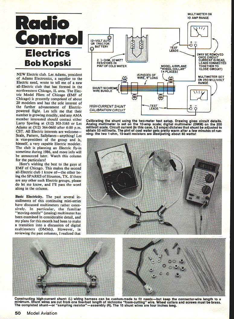
Multimeters have internal selectable shunt resistors to measure current over a wide range. Normally the lowest current range on analog multimeters is about 50 microamps; many DMMs have a lowest range of 200 microamps. The highest ranges are usually 10 amps (analog) and 2 amps (many DMMs). Motor currents often exceed these values. The shunt described here will extend capability upward to about 25 amps, covering nearly all electric‑modeling interests. The shunt pictured consists of a small bundle of short nichrome wire.
Purpose and principle
What we need is a very low‑resistance "sampling" resistor of known, stable value placed in series with one motor lead so motor current flows through it. The small resistance develops a small voltage drop proportional to the current. Since most multimeters have a low voltage scale of 200 or 250 millivolts, it's convenient to have a shunt resistance that produces about 200–250 mV at 20–25 A.
Ohm's Law: R = V / I
Example targets:
- R = 0.20 V / 20 A = 0.01 ohm (10 milliohms)
- R = 0.25 V / 25 A = 0.01 ohm (10 milliohms)
So the desired sampling resistance is roughly 10 milliohms.
Nichrome foam‑cutting wire (readily available to modelers) is convenient because its resistance is relatively stable with temperature. In contrast, copper and many metals have temperature coefficients around ±5% per 10°C, which would make the shunt resistance vary noticeably with temperature.
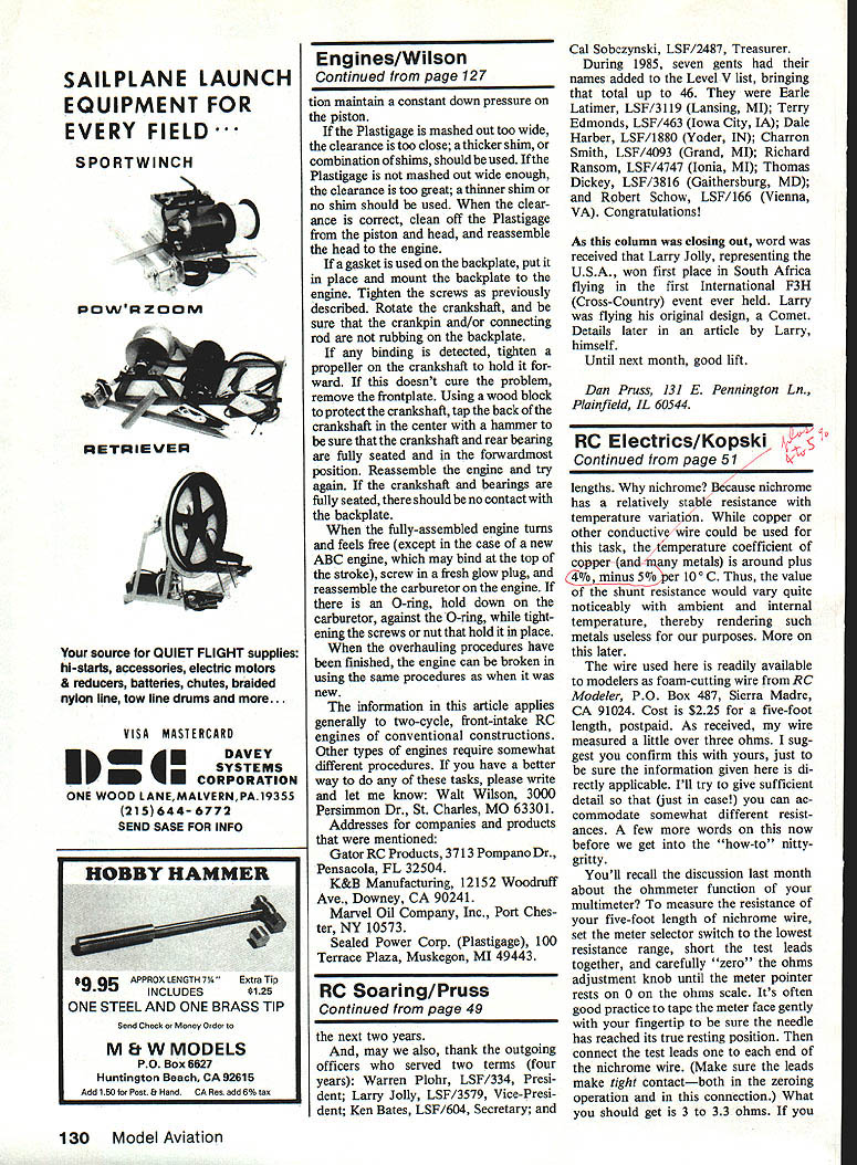
The foam‑cutting wire I used measured a little over 3 ohms for a five‑foot length (about 0.50 ohm per inch). To obtain 10 milliohms practically, I paralleled a small bundle of reasonably long pieces of wire rather than trying to cut an impractically short single piece. In my shunt I used 15 pieces, each 4 inches long, giving a bundle resistance close to 13.3 milliohms before final adjustment. The shunt is configured as a four‑terminal device: two outer current terminals and two inner voltage‑tap terminals. The inner taps are adjusted to yield the desired 10 milliohm sampling resistance.
Materials and parts (examples)
- Nichrome foam‑cutting wire (approx. 3–3.3 ohms per 5 ft as supplied)
- Four 3/8 in. brass wheel collars (no set screws initially)
- Four 6‑32 brass machine screws (ends ground smooth/deburred)
- Washers, No. 6 solder lugs, spring lock washers, 6‑32 hex nuts
- Short wiring harness / connectors (example: Molex used for Astro wiring)
- Two 1‑ohm, 10‑watt resistors (Radio Shack Cat. No. 271‑131) for calibration circuit
- Pint jar and water (for resistor cooling during calibration)
- 12‑volt battery (car or tractor battery recommended) or similar DC source
- Multimeter(s): analog on 10 A range and DMM on 200 mV range, or a single meter used in two modes
Constructing the high‑current shunt
- Cut 15 lengths of nichrome wire, each 4 inches long. Straighten them (roll individual wires between two flat pieces of wood).
- Bundle the pieces together and slip four brass wheel collars over the bundle. Position the outer collars about 1/8 in. inside the ends of the wire bundle.
- Select four 6‑32 brass screws and grind their ends smooth and slightly rounded to avoid cutting the wires when tightened.
- For the two outer collars, assemble on each screw: flat washer → No. 6 solder lug → flat washer → spring lock washer → 6‑32 hex nut (loose). Thread these screws into the outermost wheel collars and tighten so the wire bundle is squeezed tightly at each end.
- While tightening, hold the screwdriver in the screw slot and use a wrench/pliers to run the nut up against the washers and solder lugs. Do not use the wire bundle as a handle; do not loosen screws from the collars.
- Install screws into the two inner wheel collars and tighten gently. Leave the inner collars spaced approximately 1/8 in. in from each outer collar; exact spacing will be set during calibration.
- Attach wiring/harness to the solder lugs. Positive leads from connectors should be soldered to the shunt solder lugs; negative leads can be straight through. Molex connectors are convenient for easy insertion into test circuits.
Calibrating the shunt
Two methods are possible: a single‑meter method (simpler equipment) and a two‑meter method (more convenient and accurate).
Calibration goal: adjust the spacing of the inner wheel collars so the inner tap voltage equals 10 mV per amp of actual circuit current (i.e., 10 mV/A, so 25 A → 250 mV).
Calibration circuit (recommended for analog meter method):
- Two 1‑ohm, 10‑watt resistors wired in series (total 2 ohms, 20 W). Immerse resistors in a pint jar of water to increase dissipation and prevent overheating during the test.
- 12‑volt battery or equivalent DC source capable of supplying several amps.
- Multimeter(s).
Two‑meter method (preferred):
- Meter 1: connected in series on the 10 A range to read circuit current continuously.
- Meter 2: connected as a voltmeter on the 200 mV (or 250 mV) range to read the shunt tap voltage while the inner collars are adjusted.
- Adjust inner collars until the voltmeter reads V = I × 0.010 (10 mV per amp). Example: for I = 5.3 A, set V = 53 mV.
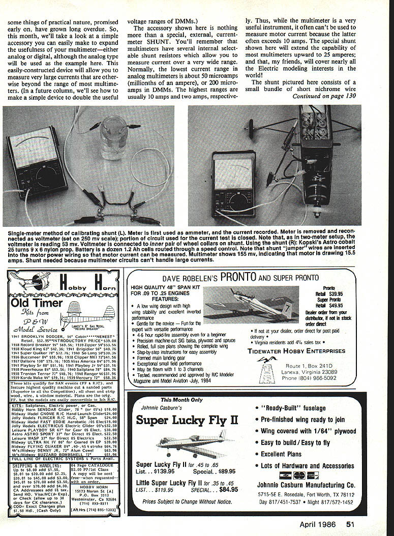
Single‑meter method:
- Configure the test circuit: battery → 2‑ohm resistor pair (in water) → shunt → back to battery.
- Use the multimeter as an ammeter on the 10 A range and record the circuit current (wait for steady reading). Example: 5.3 A.
- Remove the meter from the circuit and reclose the circuit so the resistors and shunt remain in series with the battery.
- Set the meter to the lowest voltage range (typically 0.25 V for analog meters). Connect the meter leads to the inner shunt tap collars and read the millivolt drop. Adjust inner collars until the voltmeter reads the desired shunt voltage corresponding to the current measured earlier (e.g., 53 mV for 5.3 A).
- Snug the inner collar screws when the correct reading is obtained.
Notes:
- The single‑meter method introduces a small error because the circuit changes slightly when the meter is removed and reconfigured; the two‑meter method eliminates this error and is easier.
- The shunt calibration factor becomes 10 mV per amp after adjustment.
Example of use: with Kopski’s Astro Cobalt motor (25 turns), a 9 × 6 nylon prop, and a battery of a dozen 12‑Ah cells routed through a speed control, the multimeter showed 155 mV on the shunt taps, indicating a draw of 15.5 A.
On resistance measurement and lead resistance
If you measure the five‑foot length of nichrome wire with an ohmmeter, set the meter to the lowest resistance range, short the test leads together and zero the meter, then remove the short and measure the wire. Expect around 3 to 3.3 ohms. If using a DMM, subtract any test‑lead resistance by shorting leads together tightly, noting the reading, and subtracting that from the "wire plus test leads" value.
Heat, power dissipation and material choice
In actual use at high currents the shunt will get hot because P = I^2 × R.
Example:
- If I = 25 A and R ≈ 0.0133 ohm (bundle before inner‑tap shortening), P = 25 × 25 × 0.0133 ≈ 8.33 W.
- This is comparable to a typical 7 W mini Christmas tree lamp in heat, so the shunt will be hot but should not be damaging if used as intended and not run continuously at maximum.
Nichrome is preferred because its resistance is far more stable with temperature than copper or aluminum, so the voltage reading does not change drastically as the shunt heats. If the shunt were made of copper or aluminum, resistance changes with temperature would cause significant reading errors.
Also note that the shunt introduces a small voltage drop in the motor circuit, so motor rpm may decrease slightly while the shunt is installed. This effect is more noticeable with fewer battery cells (lower system voltage).
Using the shunt with a DMM only
If you have only a DMM with a highest current scale of 2 A, calibrate the shunt using a lower calibration current. Substitute a single 10‑ohm, 10‑watt resistor (Radio Shack Cat. No. 271‑132) for the 2‑ohm set. The circuit current will be around 1.2 A and the shunt voltage about 12 mV. This pushes practical meter limits and may reduce calibration accuracy, but the shunt plus DMM combination can still offer measurement capability up to roughly 20 A because DMMs typically have a low voltage range of 200 mV.
Practical calibration circuit details
- Use a car or tractor battery as power for the calibration circuit (able to supply several amps steadily).
- The two‑ohm resistor pair will dissipate most of the 12 V supply as heat: P = V^2 / R = 12^2 / 2 = 72 W. Hence the need to immerse the resistor pair in water to prevent overheating. Do not attempt this test with the resistors in free air.
Final notes and late news
Late news: The SPARKS all‑electric club (Houston, TX) has announced their Second Spring Fun‑Fly, April 12–13, at Petrosky Elementary School. The event is AMA‑sanctioned (AMA license required to enter) and offers competitive opportunities on a low‑key basis. For more information contact Contest Director Eddie Thomas, Houston SPARKS, 1427 Ashwood Dr., Sugar Land, TX 77478 (713/491‑3375). Mention my name for extra assistance.
That's it for this month. Hope this helps those who've been asking how to measure large currents.
Any comment or question may be sent to the author (with SASE please):
Bob Kopski 25 West End Dr. Lansdale, PA 19446
Oh silent spring flights, please hurry here!
Transcribed from original scans by AI. Minor OCR errors may remain.

