
Radio Control
Electrics
Bob Kopski
CANADIAN ELECTRICS. I've just received a courtesy copy of the Electric Model Flier. This is the newsletter of the Electric Model Fliers of Southern Ontario, and if the newsletter is any indication, this is a very serious, going group. The purpose of the club and the newsletter is to further the development of the building and flying of electric-powered model aircraft. The club president is Stan Shaw, and he can be reached at 15 Aylesbury Rd., Islington, Ont., M9A 2M5, Canada. His telephone number is (416) 231-7050.
The excellently done mailing contains lots of useful information on products and "how-to" goodies, along with the normal editorial content expected of such a publication. To be perfectly candid, the issue I received puts to shame any of the columns I've done, based on the sheer volume of useful material!
The group announced the 1986 Electric Flight Symposium scheduled for March 15, 1986, which, unfortunately, will have passed by the time you read this. The long delay associated with getting something into the column is a fact of publishing life, and so I encourage anyone with a word they'd like to spread to get it to me about three months ahead of the issue date they'd like the item to appear in. As an example, this May column is being written late in January and should appear in your mail by early April.
Electric meet suggestion
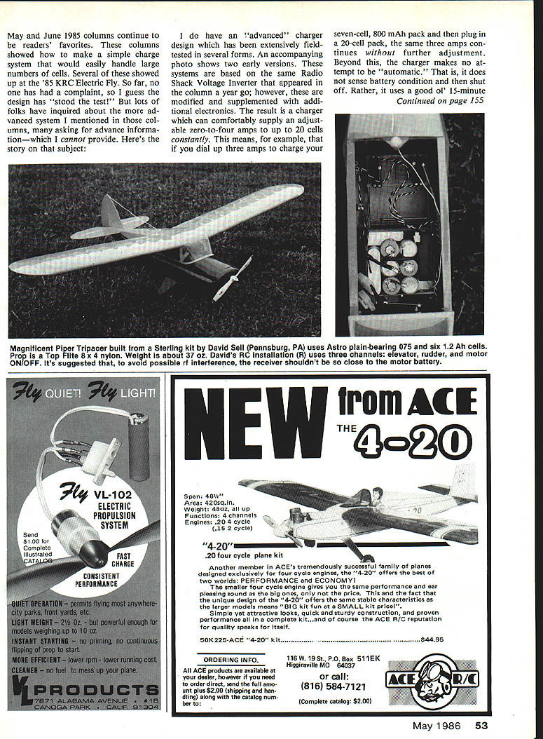
For those who may be planning an electric meet, I'd like to pass along what has proven to be a very worthwhile effort. Depending on your field layout and parking situation, it may be practical—if not necessary—to have flight-line battery charging available. In its simplest form, this can be some car batteries in the pit area. If you're expecting a lot of flying (and charging), and/or if yours is a more-than-one-day meet, you'll no doubt have to provide for charging the batteries!
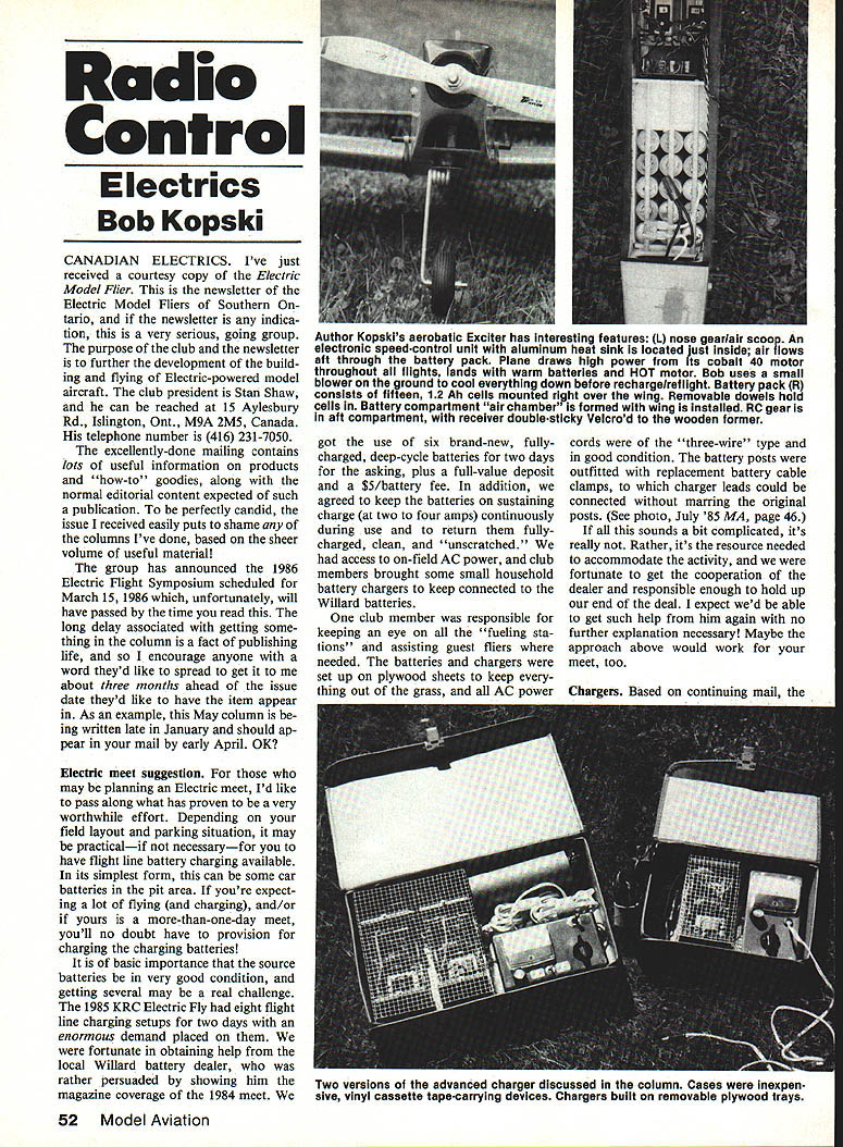
It is of basic importance that the source batteries be in very good condition, and getting several may be a real challenge. The 1985 KRC Electric Fly had eight flight-line charging setups for two days with an enormous demand placed on them. We were fortunate in obtaining help from the local Willard battery dealer, who was rather persuaded by showing him the magazine coverage of the 1984 meet. We got the use of six brand-new, fully charged, deep-cycle batteries for two days for the asking, plus a full-value deposit and a $5/battery fee. In addition, we agreed to keep the batteries on sustaining charge (at two to four amps) continuously during use and to return them fully charged, clean, and unscratched. We had access to on-field AC power, and club members brought some small household battery chargers to keep connected to the Willard batteries.
One club member was responsible for keeping an eye on all the "fuelling stations" and assisting guest fliers where needed. The batteries and chargers were set up on plywood sheets to keep everything out of the grass, and all AC power cords were of the three-wire type and in good condition. The battery posts were outfitted with replacement battery cable clamps, to which charger leads could be connected without marring the original posts. If all this sounds a bit complicated, it really is not. Rather, it's the resource needed to accommodate the activity, and we were fortunate to get the cooperation of the dealer and responsible enough to hold up our end of the deal. I expect we'd be able to get such help with no further explanation necessary. Maybe the approach above would work for your meet, too.
Chargers
Based on continuing mail, several readers have inquired about the advanced charger system I mentioned in previous columns. The subject here is an advanced charger design that has been extensively field-tested in several forms. An accompanying photo shows two early versions of the systems based on the same Radio Shack voltage inverter that appeared in a column a year ago; however, it has been modified and supplemented with additional electronics. The result is a charger which can comfortably supply an adjustable zero-to-four amps to up to 20 cells continuously. This means, for example, that if you dial up three amps to charge your seven-cell, 800 mAh pack and then plug in a 20-cell pack, the same three amps continues without further adjustment. Beyond this, the charger makes no attempt to be automatic. That is, it does not sense battery condition and then shut off. Rather, it uses a good old 15-minute timer, and that's that.
My personal preference always was (and continues to be) to charge an "empty" battery to about 90% of its label capacity—my so-named "safe charge." I'm satisfied that the automatic is OK—provided the batteries used are of the type that do display a distinct voltage peak and that everything else, like cell quality, condition, and matching, and that simple things like charge connections are near perfect—a rare occurrence.
But now for the bad news. The project article on this charger has not yet been started. A primary objective I have in such a presentation is that the parts and materials must be readily available for everyone. The chargers shown have been constructed, with very minor exception, from Radio Shack parts. Unfortunately, Radio Shack cannot be relied upon to maintain their catalog content year to year and, in fact, does constantly change some part numbers and delete others. The RC-parts situation being what it is, I opted to do basically a redesign on a more readily available foundation. I still intend to use the Radio Shack inverter, but the rest of the charger will be based on parts available at present. Some of the small electronic parts I used previously are now not readily available, and I'm faced with the major task of finding alternates that are readily available to everyone.
I won't present anything unless I've tried it myself, and rebuilding and photographing a new charger based on alternate parts is, of course, a significant effort. While I have not dropped the matter, it is getting tougher to keep my promise. Thus, at this time, I can't say for sure when such an article may appear. I am truly regretful of this, especially because of the extensive interest readers have shown.
Flight records
Members of my club have wide interests and among them is a Club Records program. The program is based on the 10 categories listed below, along with the current record in each category:
- Indoor Paper Glider — 7.8 sec.
- Indoor Rubber — 49.8 sec.
- Gas, Longest Flight — 73.0 min.
- Gas, Most Loops — 23 (per minute)
- Gas, Most Rolls — 50 (per minute)
- Gas, Most Spins — 51 (per minute)
- Electric, Longest Flight — 48 min 50 sec.
- Electric, Most Loops — 24 (per minute)
- Electric, Most Rolls — 29 (per minute)
- Electric, Most Spins — 32 (per minute)
By way of further detail and information, the indoor flying is in our normal meeting room with about a 12-foot ceiling. The paper glider can be of any design, while the rubber job is a fixed design. The loops, rolls, and spins are per minute—the pilot wrings out his best effort in front of two witnesses who tally his accomplishments for 60 seconds.
The longest flight is done by any means. For gas, that typically means a big tank. For electric, it means good piloting and luck. All planes must be flyable after the record attempt! With all this in mind, take another look at the gas and electric categories and then dare to tell me that electric doesn't work! Finally, while I once did, I no longer hold any of the records, so don't anyone think electric is only for "certain people."
At this time, I invite everyone to take a shot at bettering the electric records shown above. Please consider this a fun challenge, and I'll take your inputs as honest results and report them here from time to time. You might also like to include a photo. If it is of adequate quality, I'll try to get it in, too.
Largest meet
The January 1986 column covered the 1985 KRC Electric Fly and one offering I hesitatingly included was the speculation "...that the (meet) represents the largest RC electric meet in the world." I invited reader reaction to this, with expectation that someone somewhere would claim the honors. Not so, I guess, for the total reader reaction to date is a grand total of zero. Therefore, I now (somewhat less hesitatingly) lay claim to the 60 guest fliers from 23 states and Canada representing 95 registrations with at least 121 planes over two days as being what everyone else can shoot for. Please let me hear about it!
Basic electricity
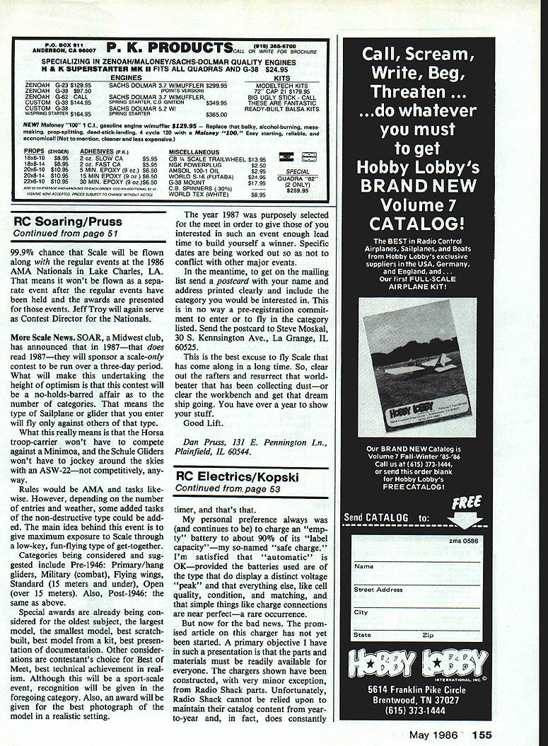
You may remember the ongoing discussion of multimeters and their operation and use. What follows now is some information about certain special functions and features of multimeters, such as the one pictured in the March '86 MA (page 52). The idea is to give you an overall warm and comfortable feeling about these handy boxes, since some folks do feel at a loss with—or even intimidated by—such "electronic stuff."
Many multimeters include other input jacks that are not included in the instruments previously pictured. These may include very-low-level voltage or current ranges, such as the 0.25-volt or 50-microamp ranges (which, in the case of the pictured meter, are included on the range-function switch).
Also, many instruments have an "output" jack, and this label can be misleading. In actuality, an "output" jack is used in conjunction with AC voltage ranges and blocks the passage of any DC component that may be present along with a varying or alternating component. Such an "output" jack has a large internal coupling capacitor in series with it. Without this, AC scales will also respond to DC, or partial DC, inputs as well. This is of no importance in modeling applications but is included here for the sake of completeness.
The particular Radio Shack instrument pictured is a favorite of mine because it offers an unusual feature—the "V-A/2" switch. In effect, this two-position slide switch nearly doubles the useful ranges of this multimeter. It works simply, but it's up to you to make sure you're reading the proper scale at all times.
It goes like this: let's say you want to read the voltage on your somewhat discharged receiver battery. You reasonably expect it to be somewhere around 4.8 volts or a little less. Set the selector switch to "10" in the "DC V" sector, and with the slide switch positioned normally in the "V-A/2" setting, connect the positive (red) lead to the battery positive terminal and the negative (black) lead to the battery negative terminal.
What you should get is about a half-scale deflection of the pointer—to about 4.8 on the 10-volt scale. Since this is less than half-scale, you can now move the slide switch to the "V-A/2" setting, and immediately the pointer will deflect about twice as far, for you have just made a five-volt range out of the 10-volt one! This action allows a sort of "magnified" reading and is available for all the voltage and current ranges on this instrument. (Most multimeters don't have this feature.) Thus, the 50-volt range can become a 25-volt range, the 2.5-volt range a 1.25-volt one, and so on for all voltage and current ranges. But do pay attention and look at the proper scale!
Most multimeter faces contain one additional scale beyond those already covered in this miniseries—a "dB" (decibel) scale. This scale is usually located closest to the meter pivot and is thus the shortest-length scale. It is used in such applications as audio systems where audio power or power-gain measurements are desired, with the results expressed in dB relative to some standard voltage and impedance level. Again, this scale is of no importance in modeling applications.
Some multimeters have a mirrored scale. This handy feature is useful in eliminating reading errors due to parallax. If one's eye is not directly over the meter pointer—such that the pointer is viewed on a slant—the scale markings are misread because they fall on a slant line of sight; that is, the observed markings are not those directly underneath the pointer. Thus, two different observers can get different readings simply because of non-identical viewing angles. The mirror eliminates this problem by allowing the user to position his eye such that the image of the pointer in the mirror disappears.
Radio Control: Electrics
That's the end of another column, folks. I hesitate to say what we'll cover next—the electric activity is too dynamic. But whatever it is, I'll do my best to "keep it comin'." Please appreciate the fact that columns are, of necessity, of limited length. Perhaps in the not-too-distant future electric will grow to sufficient size to have its own magazine. Till next time...
Please forward comment and query (with SASE, please) to Bob Kopski, 25 West End Dr., Lansdale, PA 19446.
Do be careful NOT to hit the switch while holding your electric in your lap!
Transcribed from original scans by AI. Minor OCR errors may remain.

