
RADIO CONTROL ELECTRICS
Bob Kopski 25 West End Dr., Lansdale PA 19446
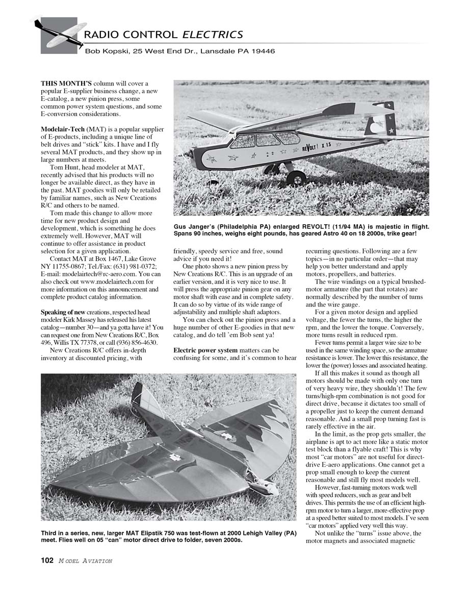
THIS MONTH'S column will cover a popular E-supplier business change, a new E-catalog, a new pinion press, some common power-system questions, and some E-conversion considerations.
Supplier change: Modelair-Tech (MAT)
Modelair-Tech (MAT) is a popular supplier of E-products, including a unique line of belt drives and "stick" kits. I own and fly several MAT products, and they show up in large numbers at meets.
Tom Hunt, head modeler at MAT, recently advised that his products will no longer be available direct as they have been in the past. MAT products will be retailed only by familiar names, such as New Creations R/C and others to be named. Tom made this change to allow more time for new product design and development, which is something he does extremely well. MAT will continue to offer assistance in product selection for a given application.
Contact MAT: Modelair-Tech, Box 1467, Lake Grove NY 11755-0867 Tel./Fax: (631) 981-0372 E-mail: modelairtech@rc-aero.com Web: www.modelairtech.com (for the announcement and product catalog)
New Creations R/C catalog and pinion press
Respected head modeler Kirk Massey at New Creations has released his latest catalog — No. 30 — and you’ll want a copy. Request one from New Creations R/C, Box 496, Willis TX 77378, or call (936) 856-4630.
New Creations R/C offers in-depth inventory at discounted pricing, with friendly, speedy service and free advice if you need it.
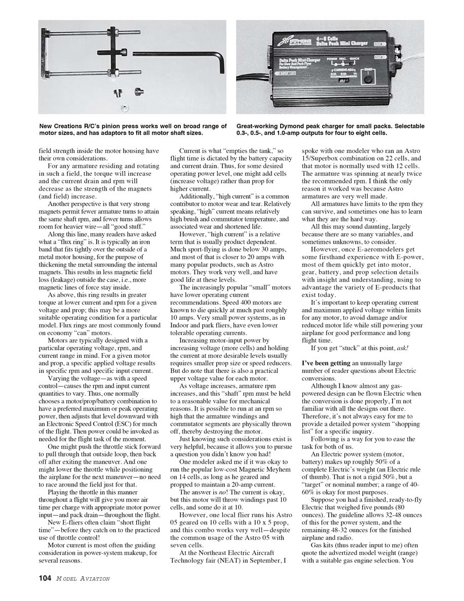
One photo in the catalog shows a new pinion press by New Creations R/C. This is an upgrade of an earlier version and is very easy and safe to use. It will press pinion gears onto motor shafts with ease thanks to a wide range of adjustability and multiple shaft adapters. Check the catalog for the pinion press and many other E-goodies — and tell them Bob sent you!
Motor windings: turns and wire gauge
The wire windings on a typical brushed motor armature (the rotating part) are normally described by the number of turns and the wire gauge. For a given motor design and applied voltage:
- Fewer turns → higher rpm and lower torque.
- More turns → reduced rpm and generally higher torque.
Fewer turns allow the use of larger-diameter wire in the same winding space, so the armature resistance is lower. Lower resistance means lower power losses and less heating. However, very few turns with high rpm are not good for direct drive because they force use of a very small prop to keep current reasonable, and small props turning fast are rarely effective in the air. This is why most "car motors" are not useful for direct-drive E-aero applications — they often need a speed reducer (gear or belt drive) so a high-rpm motor can turn a larger, more effective prop at an appropriate speed.
Motor magnets and flux rings
The strength of motor magnets and the resulting magnetic field also affect performance:
- Stronger magnets → increased torque, reduced rpm and reduced current drain for a given voltage and prop.
- Strong magnets can permit fewer armature turns for the same shaft rpm, allowing heavier wire and the benefits described above.
A flux ring is typically an iron band that fits tightly over the outside of a metal motor housing to thicken the metal surrounding the internal magnets. This reduces magnetic field leakage outside the case so more magnetic lines of force stay inside. The result is greater torque at lower current and rpm for a given voltage and prop. Flux rings are most commonly found on economy "can" motors.
Voltage, ESCs, RPM and throttle technique
Motors are typically designed for a particular operating voltage, rpm, and current range. For a given motor and prop, a specific applied voltage yields a specific rpm and input current. Varying the voltage with an Electronic Speed Control (ESC) changes rpm and input current.
Practical approach:
- Choose a motor/battery combination to give a preferred maximum or peak operating power.
- Use the ESC to reduce power for much of the flight and increase it as needed (for maneuvers, climbs, etc.).
- Practiced throttle use (pushing the stick for a task, then backing off) yields more flight time per charge and reduces pack drain.
Many new E-fliers complain about short flight time before they learn effective throttle management.
Motor current and longevity
Motor current is often the guiding consideration for power-system selection because:
- Current determines battery drain and thus flight time (battery capacity vs. current drain).
- High current contributes to motor wear (higher brush and commutator temperature → faster wear).
What "high" current means depends on the motor. Typical notes:
- Much sport flying is done below about 30 A, with many setups closer to 20 A (e.g., popular Astro motors). These work well and have good life at those levels.
- "Small" motors have lower recommended operating currents — Speed 400 motors tend to die quickly above roughly 10 A. Very small indoor/park systems tolerate even lower currents.
Increasing motor-input power by increasing voltage (adding cells) while holding current at desirable levels typically requires a smaller prop or a speed reducer. However, there is a practical upper voltage limit for each motor. As voltage increases, armature rpm increases, and excessive rpm can physically destroy the armature windings or commutator.
Examples:
- A modeler asked if a low-cost Magnex Meyhem could be run on 14 cells if a geared and propped arrangement kept current at 20 A. The answer is no: the current might be okay, but that motor will throw windings past about 10 cells (some at 10).
- One local flier runs an Astro 05 geared on 10 cells with a 10x5 prop and it works well, despite common Astro 05 usage with seven cells.
- At NEAT, I saw an Astro 15/Superbox run on 22 cells (normally used with 12) at nearly twice the recommended rpm — it worked, likely because Astro armatures are very well made.
All armatures have rpm limits, and sometimes those limits are learned the hard way.
Electric conversions: rules of thumb and what to provide
I get many reader questions about converting glow/gas models to electric. Although most gas-powered designs can be flown electrically when done properly, I can't be familiar with every design. To help me give useful power-system recommendations, follow these guidelines when asking:
- An electric power system (motor + battery) typically makes up roughly 50% of the complete electric's weight. A practical range is about 40–60% for most purposes.
- Example: a finished RTF electric that weighs 5 lb (80 oz) allows 32–48 oz for the power system and the remaining 48–32 oz for the finished airplane and radio.
- For gas kits, estimate the airplane's finished weight with radio but without the engine, tank, etc. Even better: include any weight savings you plan to make to the model. This yields the weight budget for the power system.
- Use that weight budget together with watts-per-pound and other rules of thumb to select motor, battery, and prop.
Before writing me about a specific conversion, go through these considerations. That will give me the best shot at specific power-system recommendations and get you flying most expediently. I may need additional information in some cases, and I’ll always do my best — even if that means referring you to someone more suited to your particular case.
Please enclose a stamped, self-addressed envelope (SASE) with any correspondence for which you'd like a reply.
Remember: E-power makes being an "all-season flier" easier because there's no balky engine or sticky goo to deal with in cold months. Beyond that, you can fly E-indoors almost any time. (I wonder if that counts.)
MA
Transcribed from original scans by AI. Minor OCR errors may remain.

