
RADIO CONTROL ELECTRICS
Bob Kopski, 25 West End Dr., Lansdale PA 19446
Meet announcement — Triad Electric Weekend
Colin McKinley, an active electric enthusiast from “way back,” wrote to tell me about the Triad Electric Weekend in North Carolina, scheduled for May 5–6.
This meet is hosted by two clubs: the RAMS on May 5 and the Winston-Salem Radio Control Club, Inc. on May 6. Each club will use its own field on the specified day, but both fields are available Friday, and both have primitive camping and generators.
Contacts:
- RAMS Contest Director: Nat Shepard — (704) 633-1788
- W-SRCC Contest Director: Colin McKinley — (336) 924-5890
- Meet coordinator: John Mountjoy — (336) 722-7609; E-mail: jmtjoy@triad.rr.com
Each day has lots of flying activity planned, beginning with continuous flying. Other activities include:
- Biggest Model
- Smallest Model
- Best Original
- AULD (All-Up/Last Down)
- Wingo Racing
These activities vary between the two days, so get the meet mailer from one of the contacts above. And do tell ’em Bob sent you!
Electric Connection Service
Two readers have requested listings in this column’s Electric Connection Service. The idea is to help those in E-isolated areas connect with other locals of kindred interest. This service is open to everyone—just write me and ask.
Listings this month:
- Craig Mitchell
8383 Twin Lakes Dr. S., Mobile, AL 36695 Tel.: (334) 633-6875 E-mail: lmitchell@zebra.net Craig is retired and would like to hook up with other electric aeromodelers in his area to fly closer to home.
- Bob Signorello
RD#3 Box 17-C, Meshoppen, PA 18630-9203 Tel.: (570) 833-4674 Bob is just starting in electric power and wants face-to-face opportunities with other E-modelers.
If you are in these areas, please get in touch with them — tell them “Bob sent you!”
Universal Slow Charger (USC) updates and reader reports
Reader interest in the USC continues to be high; this may become the most-built hobby electronics project I’ve shared over the years.
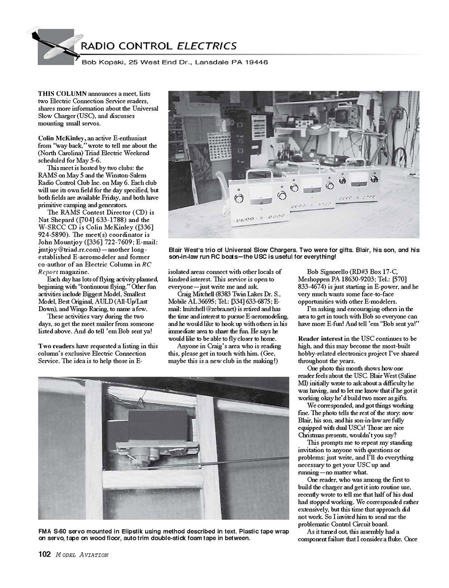
A success story: Blair West (Saline, MI) initially wrote about a difficulty he was having and said if he got it working he’d build two more as gifts. After correspondence and troubleshooting, everything worked; now Blair, his son, and his son-in-law each have dual USCs. Those make nice gifts.
If you have questions or problems with your USC, write me and I’ll do everything necessary to get your USC up and running.
A repair case: One early builder whose dual unit stopped working sent me the problematic Control Circuit board. The failure turned out to be a fluke component fault; once identified it was easy to fix and the board was returned quickly. If we can’t solve your problem by correspondence, I’m willing to take a hands-on look.
A customization: Another reader customized his dual USC with a switchable range on one of the two outputs to allow easier setting of very low currents.
USC features and low-current adjustment
As presented, the USC has:
- Fully adjustable 0–500 mA output current ranges, with options to modify for lesser values.
- An optional, readily available 0–500 mA meter to read the dialed current.
Problem: The 0–500 mA adjustment range and 500 mA meter scale make it hard to set and read very low currents (for example, the slow charge for a 50 mA pack might be roughly 5 mA, which would barely move the meter needle).
Solution (reader Al Flesher, Baltimore, MD):
- He incorporated a range switch on one output adjustment knob so the control covers either 0–500 mA or 0–50 mA.
- For meter readability at low currents, he calibrated and marked the dial for the lower range, allowing him to set low currents by the knob markings.
Al did a neat job constructing and labeling his dual USC. He sent a digital picture, which is not reproducible here. (For reproduction in print, send good-quality conventional photographs with no writing on the back.)
USC polarity and protection
Important: The USC is not reverse-battery protected. Adding that protection would have required considerable additional circuitry and cost, so it was omitted.
- Always verify battery polarity before connecting.
- One way to avoid mistakes is to use customized interconnecting cables that cannot be connected incorrectly.
- If you hook a battery up backward, the USC will attempt to charge it backward. That’s bad for the battery and may damage the USC, especially if the pack is around 20 cells or more and partially charged when connected backward.
Be forewarned: connect your battery with the proper polarity.
USC heat dissipation and transistor mounting
The USC design is highly efficient and generates very little internal heat, regardless of battery or charge current. Nevertheless, some transistors must be heat-sink mounted to the metal case to aid cooling:
- Q1 in the Advanced Power Supply option
- Q1 in each Control Circuit
Both transistors are TO-220 packages with metal mounting tabs. The tab is one of the collector connections and must be electrically insulated from the metal case, yet thermally connected for cooling. The specified mounting kit meets this dual requirement.
Mounting procedure:
- Drill a 1/8-inch-diameter hole in the metal case; keep the surrounding metal flat and free of burrs.
- Insert the 4-40 screw from outside the case.
- Place the thin rectangular mica washer (electrical insulator/thermal conductor) over the part protruding inside.
- Slip the transistor tab flat against the mica.
- Put the insulating eyelet over the screw so it enters the hole in the transistor tab.
- Fit the split lockwasher against the eyelet shoulder and tighten the nut.
The transistor will be mechanically secured, thermally coupled to the case through the mica, and electrically insulated from the case and hardware. It is not necessary to use thermal grease in the USC.
Verify with an ohmmeter that there is no electrical connection between the transistor mounting tab and the case.
Mounting tiny servos (park flyers)
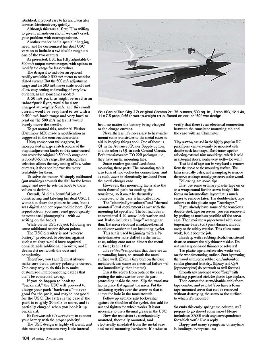
Tiny servos used in park flyers can be easily mounted with double-stick foam tape. However, the thinner auto-part double-stick tape (sold for adhering external trim moldings) adheres extremely well and can be hard to remove, often tearing balsa mounting surfaces.
Tips:
- First apply ordinary plastic tape to or as a wraparound for the servo body. This creates an intermediate layer that is easier to remove later. The double-stick tape adheres to this plastic-tape interlayer.
- If double-stick tape is already on a servo, peel off as much as possible, then moisten a paper towel with turpentine-based oil paint thinner and rub away the sticky residue. This takes work. Finish with a tissue moistened with rubbing alcohol to remove the oily thinner residue.
- Do not use lacquer-based thinners or solvents.
Mounting the tape to the wood surface:
- Treat the wood with a rubbed-on Ambroid or similar glue and let it dry (epoxy and CyA do not work as well for me).
- Smooth any hardened wood fuzz with finishing paper.
- Stick the plastic tape interlayer in place.
- Apply the double-stick foam tape and mount the servo.
This method yields a foam-tape-mounted servo that can be removed without destroying the servo or the mounting surface.
Closing
So ends this early-spring column, as I prepare to go shovel some snow! Please include an SASE with any correspondence for which you’d like a reply.
Happy and many springtime (or anytime) E-landings, everyone. MA
Transcribed from original scans by AI. Minor OCR errors may remain.

