
RADIO CONTROL ELECTRICS
Bob Kopski, 25 West End Dr., Lansdale PA 19446
2004/07
THIS COLUMN offers a communication reminder, follows up on some recent column topics, and shares reader input and questions.
Correspondence and SASE policy
As thousands of readers have learned throughout the years, I really do respond to reader mail accompanied with an SASE. I conclude every column with my invitation for you to write, and in those cases in which you want a reply, an SASE will get it for you. Of course, sometimes I get a “one-way” note that does not need a reply, and that’s fine too.
The best way to communicate with me is at the address in the column header. Please don’t write to me via MA; that just delays a response and adds to the burden of the MA staff members who have to forward your mail to me.
Also, I do not use E-mail for correspondence. Trying this route via MA also burdens the staff—and me. Just send me a letter directly and include an SASE when a reply is desired. This has been working well for everyone involved for approximately 20 years.
ACE Pro 810 / RCD Platinum receiver problem — reader follow-up
The April column had hardly hit the streets when reader reaction to the brief discussion of problematic ACE Pro 810/RCD Platinum (AM) receivers came pouring in. Sometimes readers thoroughly amaze me!
That was a nonelectric topic that I reluctantly included, and I wasn’t sure if anyone would have an interest. I’m no longer unsure; I received fast and heavy reader reaction! So to accommodate that broad-based interest, following is a review with greater detail.
The April column briefly described an intermittent problem I experienced with an old ACE Pro 810 receiver that resulted in a crash. “Intermittents” are usually the result of loose component solder connections, loose connectors, or faulty switches. The classic approach to tracking them down might include wiggling and tapping the suspect items and/or heating/cooling the suspect areas in the hopes of finding what’s wrong.
This approach did not work with what certainly seemed to be an otherwise classic intermittent receiver—in the air and on the bench. Not being one to give up, I continued to pursue the erratic operation, and this pursuit was given impetus when I found that I had another receiver displaying the same behavior on the bench.
This second receiver—associated with an unexplained crash some years past—had been on the shelf for a long time. That just made me all the more determined. It took days and a great deal of blind probing (since I didn’t have receiver drawings), but finally I found a ratty timing waveform in the decoder circuitry.
Specifically, there is a simple R-C (resistance-capacitance) network used in conjunction with the decoder IC (integrated circuit) to detect the signal frame and reset the decoder count for each frame received. The classic exponential waveform on this capacitor was jittery and of variable amplitude so that the decoder did not always reset. Simply put: it caused a crash—or maybe two.
Still thinking there was something loose in this immediate circuit area, I continued a focused wiggle and tap and heating and cooling, but no luck. It seemed as though nothing was loose. In frustration, I removed the involved capacitor from the board, and behold! It was installed backward! Then I looked at my other two Pro 810s and the similar RCD Platinum, and, sure enough, the same capacitor was installed incorrectly in all!
The capacitor is a 0.1 µF tantalum electrolytic—a polarized capacitor. Such parts must be installed with the correct polarity (as discussed in the June column). Because the actual signal levels on this component in these receivers are quite small, the capacitors actually survived the misuse for a long time.
Eventually, it appears, the backward bias caused a failure taking the form of varying capacitance value and/or a variable leakage value. Whatever it was, the fix was to remove the part, discard it, and install a replacement—correctly oriented (polarized).
Because I did not expect the high level of reader interest, I did not go into all this detail or into the corrective methodology in that April column. Now I wish I had! I did send the many readers who inquired a color printout of the receiver, highlighting the troubled capacitor, and detailed instructions regarding the replacement part.
I will supply this info to those so inquiring (who include an SASE). I did toy with including the details here, but the larger color picture I can supply is better than might be reproduced in column format.
The repair does require some desoldering/soldering skills and proper tools; it is a tightly packed board. If you feel uncomfortable with the undertaking, find a skilled friend who can help you or send it to an established RC repair service along with the descriptive sheet I can provide.
I do not know for sure that every Pro 810 and/or RCD Platinum receiver out there was manufactured incorrectly—only that my four receivers representing the two different manufacturers and purchased over time were.
Given that this issue has been addressed in an otherwise electric-dedicated column, and that surely not all MA readers read this column, I suspect that many receivers out there may be problematic for our wet-power and other flying friends. You might want to pass this discussion along to those you know who might benefit.
Since some have asked, I have never seen this problem with the predecessor ACE Silver Seven receiver, and I do not know if there is a similar consideration with the ACE Pro Star (FM) receivers.
Universal Slow Charger (USC) — reader project
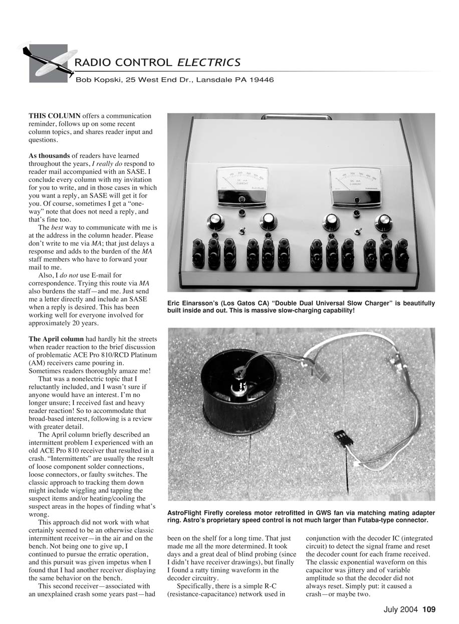
One of the most popular feature articles I’ve had published is the "Universal Slow Charger" (USC) in the September 2000 MA. I offered the USC as a "single" or "dual" version. Since then, many have built the USC in one form or another, and I’ve included an occasional reader photo. This month’s USC photo by reader Eric Einarsson of Los Gatos, CA is particularly noteworthy.
Eric expanded on the USC idea and personalized it into his "Double Dual Universal Slow Charger." Basically, he built two duals into one impressive single enclosure. That means he has four independently adjustable 0–500 mA, 1- to 42-cell outputs, each with selectable metering—all in one place. The photo showing the magnificent-looking job inside the box was unusable here.
And as many other readers have, Eric chose his preferred output connector to suit what originally published. It really makes me feel good to witness so much reader interest in such projects. My thanks to Eric for sharing this with us.
Antenna routing and noise considerations
A reader recently inquired how far away is far enough to route an antenna wire from "stuff" in the airplane. The realistic answer is that it varies.
The April and May columns included considerable discussion about noise issues and included a simple test scheme to aid in dealing with these matters. With that information as background, I can suggest that receiver antenna "dress" considerations can be studied using the same methodology.
For a given installation of receiver, servos, associated battery if any, ESC, motor, and motor battery, one can dress the antenna lead near and far from this stuff and run the bench tests described in the reference columns.
I have experienced a broad range of related effects in so doing. I have seen it possible to drape the antenna wire around and about the "stuff," and have no associated noise problems on the bench. On the other hand, I’ve seen where the antenna wire had to be routed well away from everything in the installation. So it varies.
It’s clear why there can be such a broad range of outcomes. As seen in the reference discussions, just changing a receiver brand can make a huge difference. And larger power systems are generally more capable noise sources.
Also, note that the typical power system is intimately connected to the receiver system via the ESC cable. Thus if something in a power system is a "noisemaker," that contribution might readily be found resident on servos too; it is conducted there. The only ways this would be less the case would be with the use of chokes in the ESC lead or with an optocoupled ESC.
All these are my reasons for saying "It varies" in response to that reader’s antenna dress question. If you have this concern, bench test using the technique described in the reference columns. It’s easy and helpful, although I must admit that when I first wrote it, I was not thinking about the antenna dress question.
Charging packs that have been left discharged
Another reader input was one of those one-way letters that did not need a reply. Basically, a reader named Bill wanted to tell me about some trouble he was having charging packs that had not been charged for some time.
He was routinely experiencing a fault indication of "no battery" on his peak charger display upon plugging in the pack. He found that he had to force some charge into the pack from another ("dumb") charger, and thereafter his usual charger worked normally.
Then he read the April column. Aha! Bill suddenly realized that he had one of those ESCs with an on/off switch that was not truly a "power switch." So at the end of a flying session, the connected pack was still being drained slowly by the ESC electronics so that it was truly flat dead the next time he went to fly. His charger could not recognize zero volts and indicated "no battery."
Aside from the charging annoyance that Bill experienced, it's not good at all to drain a pack (any pack) all the way. It's an instant killer for Li-Poly batteries and damaging to Ni-Cd and NiMH, although they take longer to "kill." Bill wanted me to tell everyone all about this—again.
Motor labeling and standardization
The NEAT (Northeast Electric Aircraft Technology) Fair feature in the March MA brought in several letters, including some agreeing with my comment about motor specifications/labels. On page 64 of that article, I wrote:
"...there exists an often-confusing abundance of brushless motors ... The result is that you can fly whatever you're likely to want to fly brushless, but you do have to figure out which manufacturer/product you want. As many lamented to me, this is not necessarily easy to do.
"In that respect, the industry has simultaneously done a magnificent job producing and a terrible job describing this product. As with any technically intensive consumer-product category with multiple sources, it is important for suppliers to collectively help the user use it easily. A standardized, concise, meaningful motor label would go a long way."
So why can't the motor suppliers get together and agree on some standardized label—a way to help aeromodelers understand and compare and choose among the zillion motors on the market?
What exists now—nomenclature gibberish—is worse than nothing; it's counterproductive. If it's possible to put two rovers on Mars, why is it impossible for a typical aeromodeler, who has some minimal understanding, to pick up a motor, glance at the label/part description, and immediately be able to ballpark to what application that particular motor is best suited?
Closing
This concludes another column. Please include an SASE with any correspondence—to my address—for which you'd like a reply. Everyone so doing does get one. If there is anyone out there who did this and did not hear back, I never received your letter!
Happy summertime (or anytime) E-landings, everyone!
MA
Transcribed from original scans by AI. Minor OCR errors may remain.

