

RADIO CONTROL ELECTRICS - 2004/12
Bob Kopski, 25 West End Dr., Lansdale PA 19446
THIS COLUMN BEGINS with a personal wish list of E-goodies, shares some reader questions and experiences, and describes one Dump’r "watch-out."
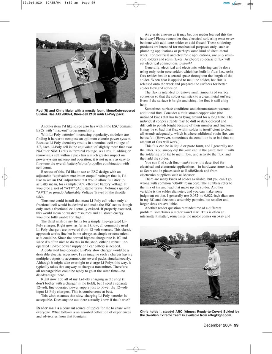
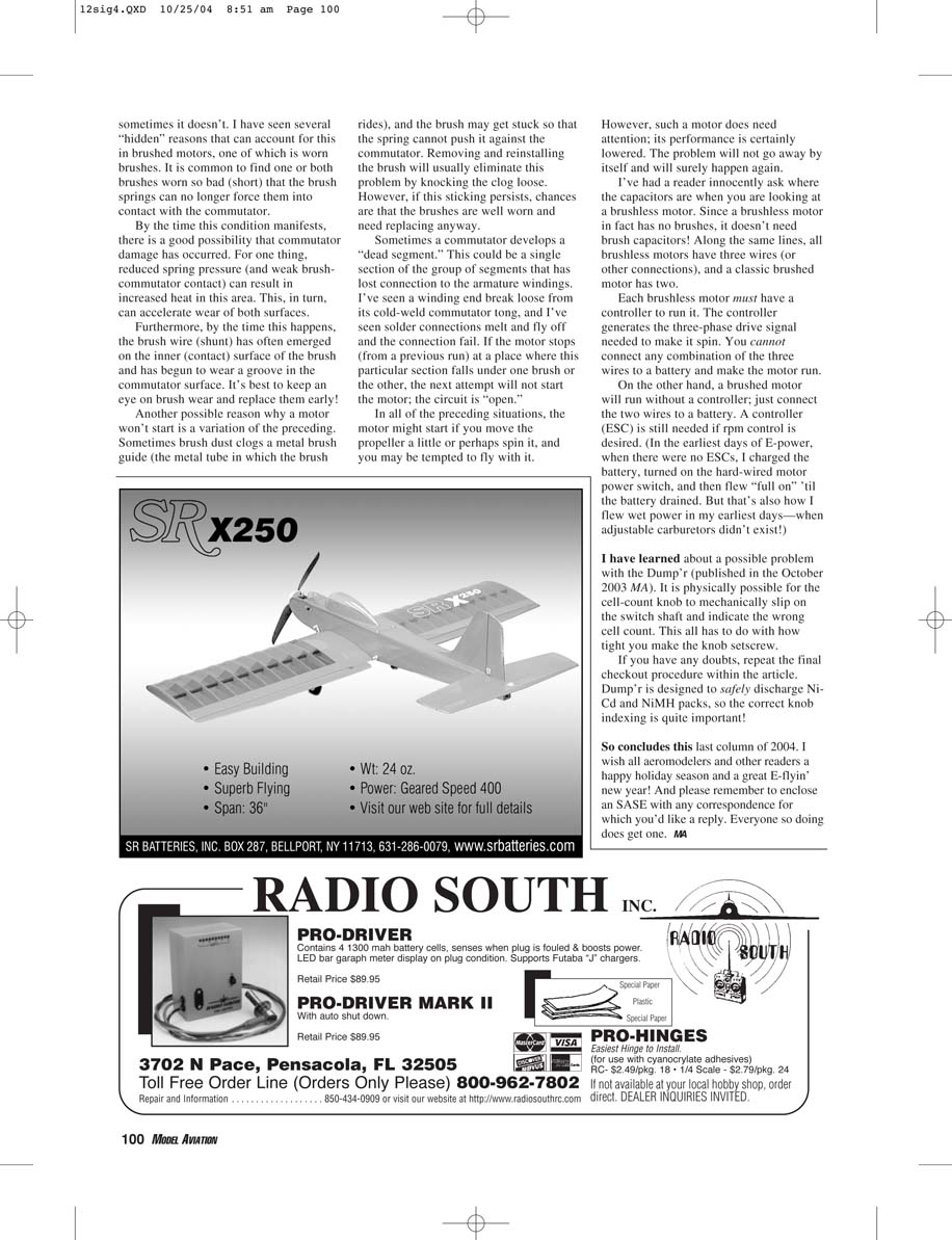
This month’s photos are from the annual LVRCS (Lehigh Valley Radio Control Society, in Easton PA) Electric Fly that took place June 5–6. This well-established meet has been growing for many years and is one of my favorites.
’Tis the season for wish lists, so it’s a good time to describe some needs that would benefit many E-aeromodelers. I’m hoping that at least some of these wishes can be realized by this time next year!
Wishes for E-aeromodelers
ESC with a better BEC
Approximately a year ago I wrote that this hobby needs an ESC with a "better BEC." All commonly used ESC/BEC products I’ve seen are limited to roughly 10 cells max for BEC use. The actual limiting number is driven by several factors including the ESC design, the number of servos in the system, and even the kind of servos in use. Most of these speed controls can be used with much higher cell counts when the BEC is not used.
The BEC-driven cell-count limitation is because of heat generated mostly during servo operation. At this time the current demand is greatest, and this current multiplied by the voltage difference on the BEC regulator device is power that produces heat within the circuit. Linear regulator integrated circuits are commonly used to power the radio gear, so these parts get hot. In fact, they can get disastrously hot.
I see a simple way around this—at least in principle. If the BEC regulator were of switch-mode design, there would be little power loss (heat) associated with radio and servo operation. The cell-count limitation would essentially disappear, so even the largest electrics could benefit from the availability of a BEC—just as smaller models do now.
At roughly the time I covered this topic, I reported that at least one manufacturer was planning such an ESC/BEC product. This has not come to pass, so switch-mode BEC ESCs continue to be on my wish list.
ESCs with adjustable "max-out"
Another item I’d like to see also lies within the ESC domain: ESCs with "max-out" programmability. With Li-Poly batteries’ increasing popularity, modelers are finding it harder to design an optimum electric power system. Because Li-Poly chemistry results in a nominal cell voltage of 3.7 V, each Li-Poly cell is equivalent to slightly more than two Ni-Cd or NiMH cells in terminal voltage. As a result, adding or removing a cell within a pack has a much greater impact on power-system makeup and operation; it is not nearly as easy to fine-tune the overall battery/motor/propeller combination with cell count.
Because of this, I’d like to see an ESC design with an adjustable "equivalent maximum output" voltage; that is, an ESC adjustment that would allow full stick to actually mean, for example, 90% of the effective battery voltage. It would be a sort of "ATV" (Adjustable Travel Volume) concept applied to voltage—call it "AVT" (Adjustable Voltage Travel) on the throttle stick. Thus one could install an extra Li-Poly cell when only a fractional cell would be desired and make the ESC act as though only such a fractional cell existed. If properly executed, this would mean no wasted resources and all stored energy would be fully usable for flight.
Line-operated Li-Poly slow charger
The third wish on my list is for a simple line-operated Li-Poly charger. Right now, as far as I know, all commonly sold Li-Poly chargers are powered from 12-volt sources. This classic approach works fine but is not always as simple or convenient as it could be. Since the normal highest charge rate is 1C and since it's often nice to do this in the shop, either a robust line-operated 12-volt power supply or a car battery is needed.
A dedicated line-operated Li-Poly slow charger would be a desirable accessory. I can imagine such a charger having multiple outputs to accommodate several packs simultaneously. Although it might take overnight to charge Li-Polys this way, it typically takes that long anyway to charge a transmitter. Therefore, all rechargeables could be ready to go at the same time—no disadvantage here.
Right now I do all of my Li-Poly charging in the shop (I don't bother with a charger in the field), but I need a separate 12-volt, line-operated power supply just to power the 12-volt-input Li-Poly chargers. This is cumbersome at best.
This wish assumes that slow-charging Li-Poly batteries is acceptable. Does anyone out there actually know if that's true?
Reader mail and advisories
Soldering: never use acid-core
Reader mail is a constant source of topics for me to share with everyone. As classic a no-no as it may be, one reader learned this the hard way: electrical soldering must never be done with acid-core solder or acid fluxes! These soldering products are intended for mechanical purposes only, such as plumbing applications or sheet-metal work. For electrical and electronic applications, use only rosin-core solders and rosin fluxes. Acid-core solder/acid flux will eat electrical connections to death.
Generally, electrical and electronic soldering can be done using only rosin-core solder, which has built-in flux; i.e., rosin flux resides inside a central space throughout the length of the solder. When heat is applied to melt the solder, hot flux is released onto the work and prepares the surfaces for better solder flow and adhesion.
The flux is intended to remove small amounts of surface corrosion so that the solder can stick to a clean metal surface. Even if the surface is bright and shiny, the flux is still a big help.
Sometimes surface conditions and circumstances warrant additional flux. Consider a multistrand copper wire (the untinned kind) that has been lying around for a long time. The individual copper strands may be dull or dark-colored and difficult to polish bright because of their number and fineness. It may be so bad that flux within solder is insufficient to clean all strands adequately, which is where additional rosin flux can be useful. (However, sometimes the condition is so bad that no amount of flux will work.)
This flux can be in liquid or paste form; I generally use the paste. You simply dip the wire end in the paste, heat it with the soldering-iron tip to melt, flow, and activate the flux, and then add the solder.
You can find such flux—make sure it is described for electrical and electronic applications—in hardware stores such as Sears, in places such as RadioShack, and from electronics suppliers such as Mouser.
There are many kinds of solder available, but you can't go wrong with common "60/40" rosin-core. The numbers refer to the mix of tin and lead that make up the solder. Another consideration is solder diameter; you can make some judgment on that. I generally use 0.032- to 0.022-inch diameter in my RC and electronic assembly pursuits, but smaller and larger sizes are available.
Why a motor sometimes won't start
Another reader question reminded me of a different problem: sometimes a motor won't start. This is often an intermittent matter; sometimes the motor comes on okay and sometimes it doesn't. I have seen several "hidden" reasons that can account for this in brushed motors, one of which is worn brushes. It is common to find one or both brushes worn so short that the brush springs can no longer force them into contact with the commutator.
By the time this condition manifests, there is a good possibility that commutator damage has occurred. For one thing, reduced spring pressure (and weak brush-commutator contact) can result in increased heat in this area. This, in turn, can accelerate wear of both surfaces.
Furthermore, by the time this happens, the brush wire (shunt) has often emerged on the inner (contact) surface of the brush and has begun to wear a groove in the commutator surface. It's best to keep an eye on brush wear and replace them early.
Another possible reason a motor won't start is a variation of the preceding. Sometimes brush dust clogs a metal brush guide (the metal tube in which the brush rides), and the brush may get stuck so that the spring cannot push it against the commutator. Removing and reinstalling the brush will usually eliminate this problem by knocking the clogs loose. However, if this sticking persists, chances are that the brushes are well worn and need replacing anyway.
Sometimes a commutator develops a "dead segment." This could be a single section of the group of segments that has lost connection to the armature windings. I've seen a winding end break loose from its cold-weld commutator tang, and I've seen solder connections melt and fly off and the connection fail. If the motor stops (from a previous run) at a place where this particular section falls under one brush or the other, the next attempt will not start the motor; the circuit is open.
In all of the preceding situations, the motor might start if you move the propeller a little or perhaps spin it, and you may be tempted to fly with it. However, such a motor does need attention; its performance is certainly lowered. The problem will not go away by itself and will surely happen again.
Brushless motors vs. brushed motors
I've had a reader innocently ask where the capacitors are when you are looking at a brushless motor. Since a brushless motor in fact has no brushes, it doesn't need brush capacitors! Along the same lines, all brushless motors have three wires (or other connections), and a classic brushed motor has two.
Each brushless motor must have a controller to run it. The controller generates the three-phase drive signal needed to make it spin. You cannot connect any combination of the three wires to a battery and make the motor run.
On the other hand, a brushed motor will run without a controller; just connect the two wires to a battery. A controller (ESC) is still needed if RPM control is desired. (In the earliest days of E-power, when there were no ESCs, I charged the battery, turned on the hard-wired motor power switch, and then flew "full on" until the battery drained. But that's also how I flew wet power in my earliest days—when adjustable carburetors didn't exist!)
Dump’r watch-out
I have learned about a possible problem with the Dump’r (published in the October 2003 MA). It is physically possible for the cell-count knob to mechanically slip on the switch shaft and indicate the wrong cell count. This all has to do with how tight you make the knob setscrew.
If you have any doubts, repeat the final checkout procedure within the article. Dump’r is designed to safely discharge Ni-Cd and NiMH packs, so the correct knob indexing is quite important!
Closing
So concludes this last column of 2004. I wish all aeromodelers and other readers a happy holiday season and a great E-flyin' new year! And please remember to enclose an SASE with any correspondence for which you'd like a reply. Everyone so doing does get one. MA
Transcribed from original scans by AI. Minor OCR errors may remain.

