
Radio Control: Electrics
Bob Kopski
BLEAK! It is late October, and winter lies just ahead. Naturally, "the bleak of winter" only means something to those folks who have to put up with it — i.e., those who have to forgo flying several times a week because the snow, wind, and cold discourage such aeromodeling pursuits.
Electric fliers, take heart: electric power works very well in the cold and, short of shaking loose some snowflakes, there's no gooey cleanup to contend with. I've been flying electric year‑round since 1972 (March 1987 is my fifteenth anniversary of flying electric), and there is essentially no problem beyond personal discomfort. Fly as usual, except for one thing: if your packs have been stored in an unheated area and the storage temperature has been below freezing, warm the battery pack a little before charging. Some readers have experienced problems with packs accepting a charge when extremely cold; I conclude these problems occur when pack temperature drops below freezing. If that sounds like your situation, take heed.
A further reminder: cold batteries may deliver normal flight performance if used quickly because the battery warms up during flight. I have experienced several first flights of the day where the plane was sluggish for two or three minutes after launch, then almost suddenly pepped up as the battery warmed. Thereafter, performance was normal for the session.
Motor mounts — Leisure Lanzo Bomber
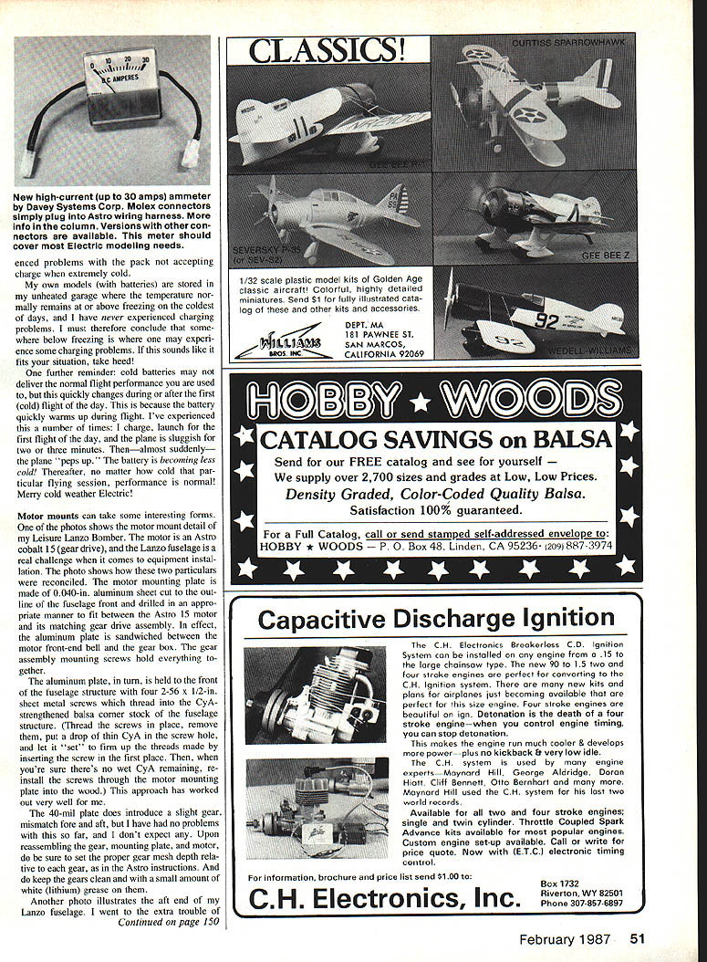
Motor mounts can take interesting forms. On my Leisure Lanzo Bomber the motor is an Astro Cobalt 15 (geared drive) and the Lanzo fuselage presents a real challenge for equipment installation. I used a motor mounting plate made from .040‑in. aluminum sheet cut to the outline of the fuselage front and drilled to fit between the Astro 15 motor and its matching gear drive assembly. In effect, the aluminum plate is sandwiched between the motor front‑end bell and the gearbox; the gear‑assembly mounting screws hold everything together.
The aluminum plate is held to the front bulk of the fuselage with four 2‑56 x 1/2‑in. sheet‑metal screws which thread into CyA‑strengthened balsa corner stock. Recommended procedure:
- Thread the screws into place to form the threads in the wood, then remove them.
- Put a drop of thin CyA in each screw hole and let it set to firm up the newly formed threads.
- When there is no wet CyA remaining, re‑install the screws through the motor mounting plate into the wood.
This approach has worked very well for me. The .040‑in. plate does introduce a slight gear mismatch fore and aft, but I have had no problems and do not expect any. When reassembling the gear, mount the plate and motor and be sure to set the proper gear‑mesh depth per the Astro instructions. Also keep the gears clean and use a small amount of white (lithium) grease on them.
Battery cooling and tail mounting
I added a battery‑cooling air outlet duct in the bottom side of the fuselage ahead of the stabilizer. I had been experiencing excessive battery heat buildup due to lack of airflow through the battery pack. After creating front air inlets and the aft air exits, air flows through the battery area during flight and brings pack temperature back to a reasonable level by landing.
I also went to the extra trouble of rubber‑mounting the tail assembly. I often bump tails in transit and sometimes break balsa when the tail is rigidly glued in place. A little rubber can prevent needlessly lost flying opportunities — consistent with my "fly more, fix less" philosophy.
Motor modifications — Astro Cobalt 05 and 15
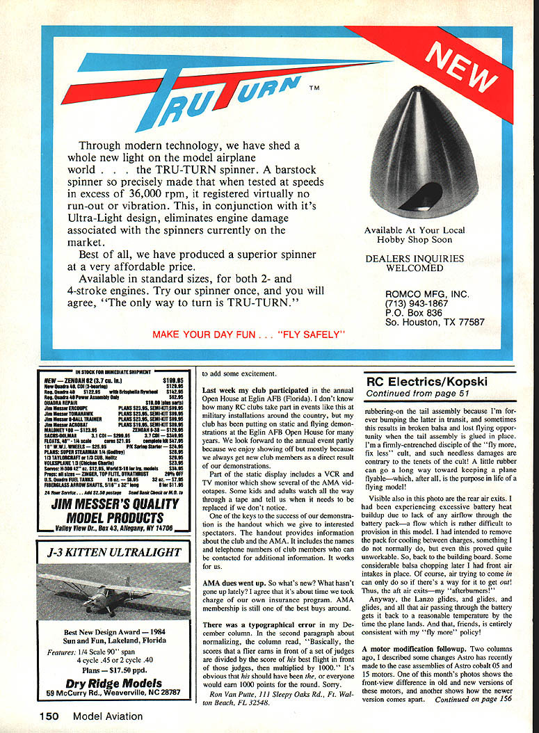
Astro recently changed the assemblies on the Cobalt 05 and 15 motors. The newer version has two through‑bolt screw heads visible on the front end bell; these bolts run nearly the length of the motor and thread into the rear end bell, holding the entire case assembly together. Removing the screws allows easy disassembly of the motor housing — but be sure to remove the brushes first.
Loosening the through‑bolts slightly allows the brush position to be rotated a bit with respect to the field magnets, which changes brush angle and thus modifies motor performance. I hope to provide fuller particulars on this procedure in a future column. In the meantime, if you're not sure what you're doing, don't do anything. Also note that the newer motor versions have dimensional changes such that "old" and "new" armatures and rear end bells are not interchangeable; specify which version you have when ordering replacement parts.
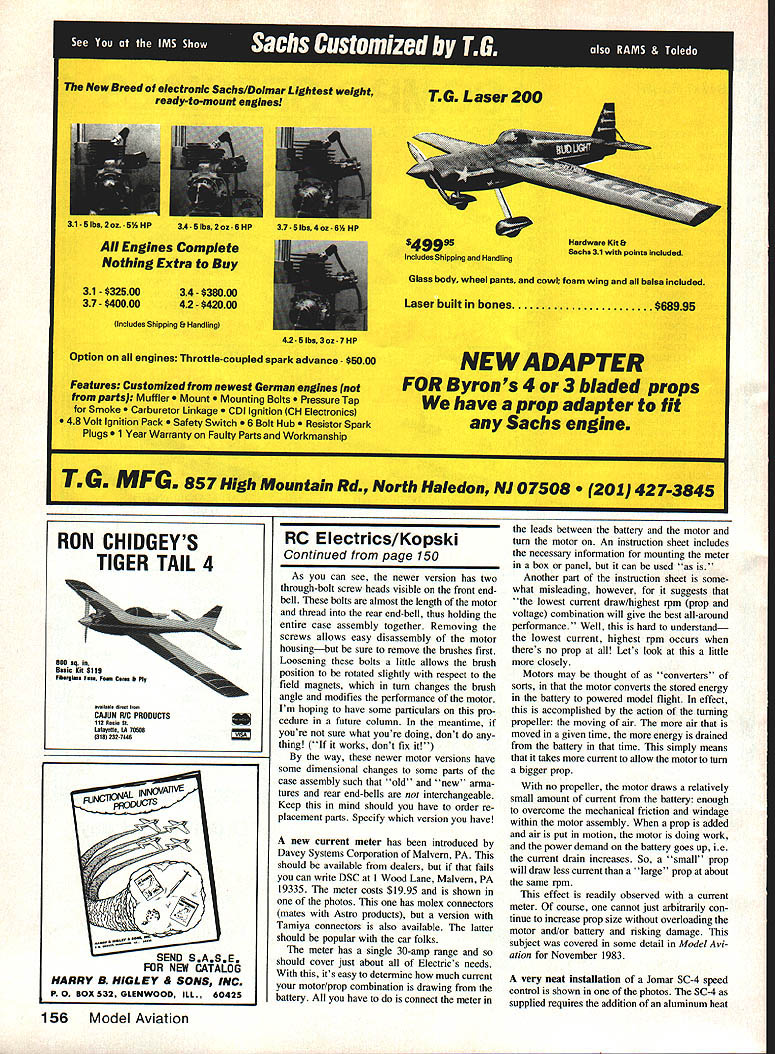
Current meter — Davey Systems Corporation
Davey Systems Corporation (DSC) of Malvern, PA has introduced a new current meter. It should be available from dealers; if not, write DSC at 1 Wood Lane, Malvern, PA 19355. The meter costs $19.95 and is shown in one of the photos. It has Molex connectors (mates with Astro products); a version with Tamiya connectors is available and should be popular with car fliers. The meter has a single 30‑amp range, covering most electric needs.
Using the meter is simple: connect it in series between the battery and the motor and turn the motor on to read current draw. The instruction sheet includes mounting information for box or panel installation, but it can be used "as is."
One caution: part of the instruction sheet is misleading in suggesting that "the lowest current draw/highest rpm (prop and voltage) combination will give the best all‑around performance." That statement is misleading because a motor with no prop at all will show low current and high rpm but does no useful work. Motors convert battery energy into useful work by moving air; the more air moved in a given time, the more power is required and the more current is drawn. Thus a larger prop will draw more current at similar rpm than a smaller prop. You cannot arbitrarily increase prop size without risking overstress to the motor or battery. This topic was covered in Model Aviation, November 1983.
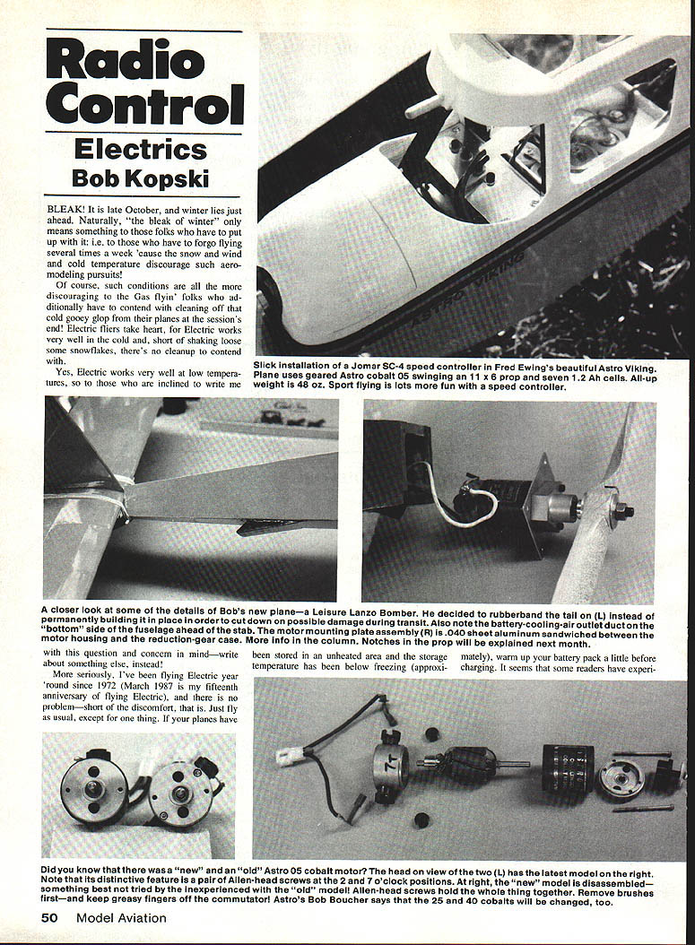
Speed controllers and electronic brake
A neat installation of a Jomar SC‑4 speed controller is shown in one photo. The SC‑4 requires an aluminum heat sink to keep the power MOSFETs cool. Local electric flier Fred Ewing cut an aluminum plate to fit crosswise in his new Astro Viking and attached it to two balsa rails with four small sheet‑metal screws. The speed control PC board hangs down into the fuselage, positioned just inside the fully open cabin front so plenty of air flows past the cooling plate and onward through the battery pack and out the fuselage bottom. The side windows are covered with clear MonoKote. A speed control always adds another dimension to electric flying because power may be applied as required for the desired flight behavior instead of being simply on or off.
Some speed controls, such as Jomar's SC‑3, offer a built‑in electronic brake to rapidly stop prop rotation when power is shut down (useful with large folding props). However, many modelers allow the unit to "slam" the motor — full on to full off with no coast‑down time. This dumps the rotational energy of the armature, gears, and prop into the brake MOSFET, which can fail under the abusive energy surge.
A much less destructive technique is to more slowly reduce applied power and then move to full off. This allows rotational energy to dissipate and prolongs the life of the brake MOSFET. This advice applies generally to any speed control with an electronic brake feature.
That's it for another fun month.
Please forward any comment or question (with SASE, please) to: Bob Kopski 25 West End Dr. Lancaster, PA 19406
Here's wishing you a very happy and safe Electric New Year!
Transcribed from original scans by AI. Minor OCR errors may remain.

