
Radio Control: Electrics
Bob Kopski 25 West End Dr. Lansdale, PA 19446
Second Annual Electric Fly-In (Winston-Salem R/C Club)
An event for all you electric fliers to look forward to is the Second Annual Electric Fly-In of the Winston-Salem (NC) Radio Control Club, Inc., which I mentioned in this column last month. I just received additional information for that August 20–21 meet.
- The CD (Contest Director) is Charles Spear, 288 Holly Lane, Mocksville, NC 27028. I've met Charles at a KRCC meet; he's a fine person and I know this should be a fine meet. If you write to him you can get a mailer which includes the meet description and a detailed map to the field, called Thrift Field, located in Advance, NC.
- Meet activities include prizes for the Most Aerobatic and Beauty events (the latter for flying scale and attractive models). Frequency qualifying will take place on Saturday for the All-Up/Last-Down event on Sunday. The winner of this activity goes home with $50 (watch out for John Mountjoy!).
- Other particulars include transmitter impound, frequency control pins, flight-line charging, on-field assistance (bring your electric questions and troubles), refreshments, rest facilities, nearby motels and campsites, and a casual, relaxed atmosphere.
When you write Charlie, tell him Bob sent you!
Magazine Coverage and a Paradox
Where did they all go? I don't get every model magazine every month, but over time I sample them all. It's obvious that electric is enjoying rapid growth—clearly evidenced by the steady increase in magazine ads for electric kits and products. Yet, while about two years ago all five of the popular monthlies carried regular, dedicated electric columns, it now looks like only two remain in print: Model Builder and, of course, Model Aviation.
To me this is a paradox of simultaneous growth and decline. Can anyone out there explain this?
Electric Old-Timer Rules
Since I'm asking for help, here's another question. A reader in California sent me a copy of some Electric Old-Timer rules developed by cooperating SAM groups. As written, these particular rules form the basis for the 1988 interim electric power rules. A review will be conducted in 1989 to evaluate the rules' suitability.
These rules are quite detailed. Some stipulate the normal SAM requirements regarding model suitability (minimum wing loading, etc.). Others include specifics such as frame diameter 35 mm, frame length 49 mm maximum; armature displacement 95 cc maximum; must have a three-bar commutator—unusual stuff. Beyond this are different specifications for non-ferrite motors (see the April 1987 issue of Model Aviation).
I can't believe anyone would deny fellow modelers electric fun. I don't understand the rationale behind such restrictive rules. SAM folks are generally superb modelers whom I know personally and rank among the finest people I've met; I just can't figure out why fun-loving folks would want such anguishing rules.
Therefore I'm asking anyone who can explain the situation to kindly write and enlighten me. I'll pass any good information along in a future column so everyone can share the reasoning. I made the same request back in the August 1985 issue when earlier Old-Timer rules proposals (creative ones like counting gear teeth) got zero reader feedback. Maybe I'll be luckier this time.
Meanwhile, readers interested in participating in this sort of original research can disassemble their motors, immerse the armature in a suitable liquid contained in calibrated glassware (just like in high school physics), and determine the "displacement" to see if they are "legal." Ah—then you can estimate how long it should take to pump up the pack.
Charge Time Formula
Simplifying the math:
0.03 × mAh = charge time in minutes
(Charge time in minutes = 3% of the cell capacity in mAh)
Typical Charge Times
- Ni-Cd cells (mAh → minutes):
- 250 mAh → 7.5 minutes
- 500 mAh → 15 minutes
- 900 mAh → 27 minutes
- 1,200 mAh → 36 minutes
- Lead-acid cells (not gel-cells) (Ah → hours):
- 6 Ah → 3 hours
- 12 Ah → 6 hours
I use a watch to monitor how long charging has been going on. If the charger shuts off early, I push the Start button again. If you are worried about overcharging, feel the pack: if it is cool, it is safe to push the Start button. In fact, anytime the pack is cool and the VR light isn't glowing, push the Start button.
The Ace R/C Overnighter
Every set of Ni-Cd charging instructions says the same thing: "Charge 24 hours, using the charger provided, before using the device; then charge overnight (14 hours) at least monthly." This is necessary because Ni-Cd cells must form the ability to hold a charge, and that happens slowly. You only can be successful with a fast charger after the cells have "formed." So where does that leave me with the TRC?
There are times when you want to "set it and forget it" (i.e., slow charge overnight). You don't want to sit there with a stopwatch. For those times I bring the palm-sized Ace R/C Overnighter. It plugs into the van's 12 V DC cigar lighter on one side and into two transmitters and two receiver packs on the other. Charging proceeds via the 14-hour rate, whether the van engine is running or stopped. This can be useful because the TRC fast charger instructions specifically prohibit use when the engine is running.
The Overnighter is a voltage-regulated, constant-current charger which can be internally programmed to charge battery packs with mAh ratings of 250, 500, 900, or 1,200. It takes almost no room, is contained in a rugged metal case, and it gets the job done. Ace or R/C Interconnect kit 34K50 ($24.95) or assembled unit 34K50C ($33.95), from Ace R/C, Inc., PO Box 511E, Higginsville, MO 64037; (816) 584-7121.
Connectors and Tools
I know what you are thinking: "How does he handle all of those special charging plugs?" Very simple. I cut them off, then put them back on with Deans connectors (available from Ace R/C). Then all I have to take along is the special connector—not the whole 110 VAC charger.
To monitor what's going on, I have the Accu-Tab 2A (described in my April 1988 column), with my universal adapter, the "Ugly Octopus" (described in my March 1982 column). For electronic repairs, I'll carry the Porta-soldering iron (see my February 1988 column).
Personal Note
Well, that's it for this month. You know what I plan to do about charging batteries, and why. Don't expect quick answers to your letters for the next few months, because I won't be receiving the mail. I sold the house to my son, and I'm off to see the world!
Heck! On second thought, just drink the stuff in the glassware instead—it's gotta be more fun!
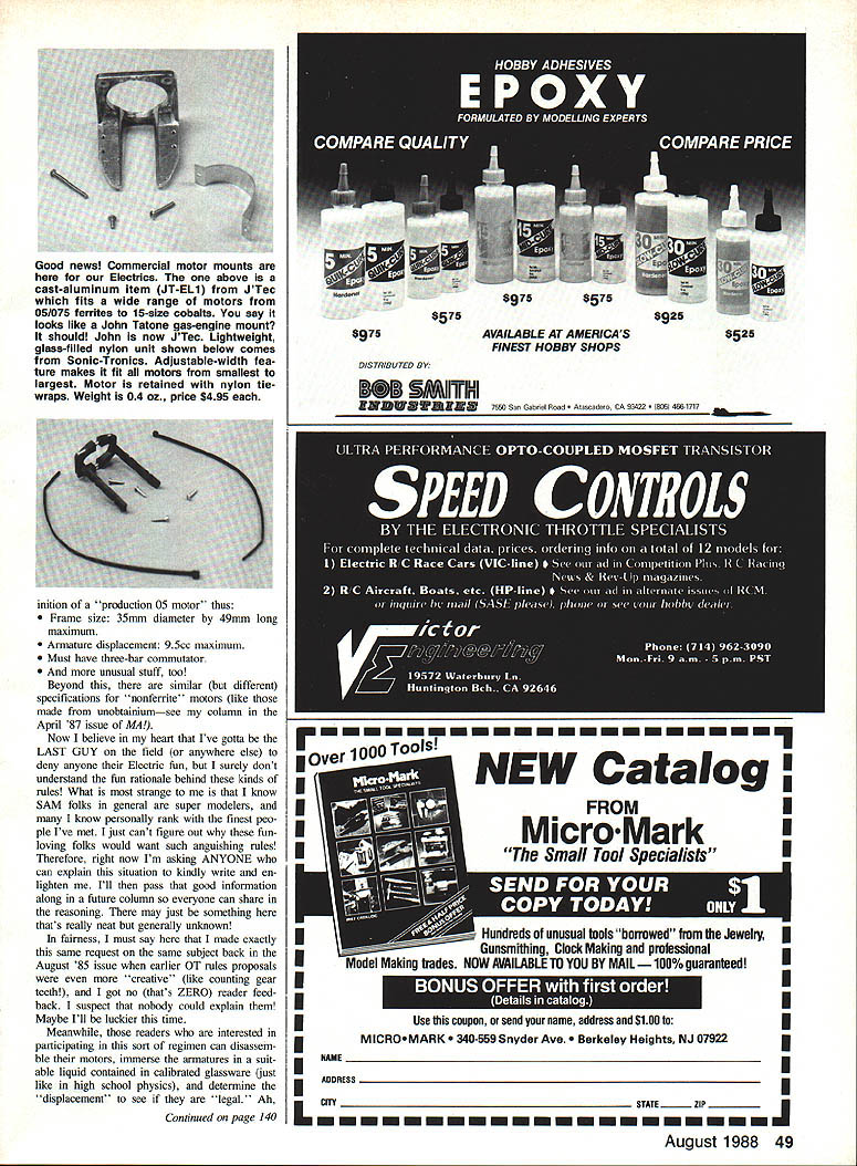
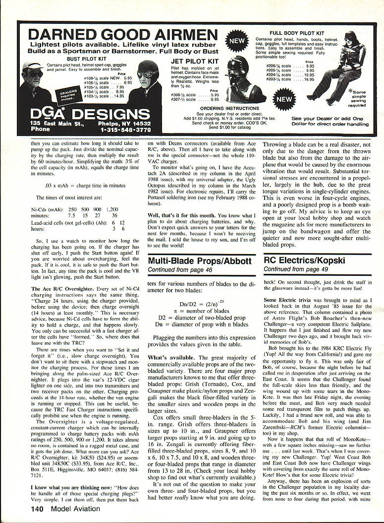
Challenger Trivia
Some electric trivia was brought to mind as I looked back at the August 1985 issue for the above reference. That column contained a photo of Astro Flight's Bob Boucher's then-new Challenger—a very competent electric sailplane. I just finished and flew my new Challenger (two days ago), and it brought back vivid memories of Bob's.
Bob brought his to the 1984 KRCC Electric Fly (yes—he came all the way from California!) and gave me the opportunity to fly it. This was only fair because the night before he had some bad luck after just arriving on the East Coast: the Challenger found the full-scale skies less than friendly and he wound up with some torn bits in the MonoKote. It was late Friday night, the evening before the meet, and Bob needed red transparent film to patch things up. Luckily, I had a brand-new roll, and was able to accommodate Bob and his wing (and Jim Zarembski—RCM's fierce electric columnist—did some help too).
That roll of MonoKote—with a few search wrecks and misses—was very useful just last week when I converted my new Challenger. West Coast Bob and East Coast Bob now have Challenger wings with coverings from exactly the same roll of MonoKote! How's that for some electric trivia?
We've had an explosion of Challengers locally in the past six months: we went from none to four, with mine being the last one. The small Challenger has become one of the most popular electric sailplanes—its clean lines and good performance make it attractive.
All four of ours are presently outfitted with geared cobalt 05s (ugh—there's that detestable design criticism again) on seven-cell packs of various capacities, swinging various sizes of K&W folding props. Mine is configured with an easily accessed variable motor mounting and a versatile battery compartment so I can play with a variety of power systems. As time goes on I'll have more information to pass along.
One simple, useful tip: four of the local Challengers turned out a bit nose-heavy. Keep this in mind as you arrange your radio installation and position gear as far aft as possible.
Finally, those of you who have built Challenger kits no doubt saw the photos in the kit instruction manual. The manual was written after the 1984 KRCC meet, and some photos therein were taken at that meet. I can assure you the plane pictured flies very well—because I flew it!
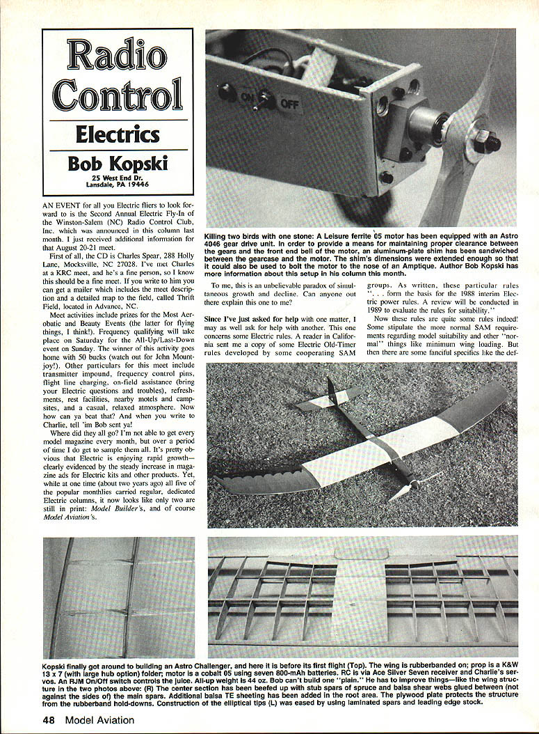
Astro 4046 Gear Drive and Pinion Removal
The Astro 4046 gear drive for .02/.035 motors was enthusiastically described in my March and June 1988 columns. The June column discussed one approach to pinion gear removal and replacement. It turns out Mitch Poling, Model Builder's electric power columnist, also has good words to say about the drive (see his May 1988 column).
Mitch refers to a gear puller made by BoLink, a major supplier to model car enthusiasts. He says their 5/16 Model BL6014 puller does a good job and is well worth the money. Write to BoLink, 420 Hosea Rd., Lawrenceville, GA 30245. You might also try hobby stores catering to model cars for it. I have not seen this product, but if Mitch says it's good, it's good. And if you're not reading the electric column in Model Builder, you should be!
My June 1988 column also discussed mounting the drive to 05s using a shim to properly space the motor and drive housing for proper gear mesh. One modeler used a square of aluminum about 30–40 mils thick, with suitable cutouts to clear the motor shaft and screws, sandwiched between the gear drive housing and the motor front-end bell. The metal plate was then screwed onto an Amptique firewall. Neat! A similar mounting method used with a cobalt 15 and its gear drive was pictured in this column in February 1987.
Motor/Propeller Performance Data
Last month's column offered motor performance data for six cobalt 15s using direct drive. This month I offer static performance data for geared cobalt 05s and 15s with different folding props. I recently took this data while deciding what motor to install first in my new Challenger.
For those technically inclined, refer to last month's column for a discussion of how I take such data. For everyone in general, this information can offer guidelines should you wish to use any of these motor/prop combinations.
Two notes:
- All props used were assembled with the "large" K&W hub. A shorter-hub option (which effectively reduces the diameter a little from that listed) is also available.
- All data below was taken with neutral motor-brush timing.
#### Geared Cobalt 05 with K&W Folding Prop
- Prop 11 × 7
- Volts: 4.57, Amps: 12.3, RPM (×1000): 4.3, Power in (watts): 70
- Volts: 5.27, Amps: 15.3, RPM (×1000): 4.5, Power in (watts): 81
- Volts: 5.91, Amps: 18.0, RPM (×1000): 4.6, Power in (watts): 106
- Prop 12 × 7
- Volts: 6.05, Amps: 21.3, RPM (×1000): 5.5, Power in (watts): 142
- Volts: 6.18, Amps: 21.5, RPM (×1000): 5.0, Power in (watts): 132
#### Geared Cobalt 15 with K&W Folding Prop
- Prop 12 × 7
- Volts: 8.14, Amps: 7.8, RPM (×1000): 4.5, Power in (watts): 60
- Volts: 9.06, Amps: 10.2, RPM (×1000): 5.4, Power in (watts): 102
- Volts: 10.02, Amps: 11.6, RPM (×1000): 5.5, Power in (watts): 119
- Volts: 11.45, Amps: 14.1, RPM (×1000): 5.8, Power in (watts): 161
- Prop 13 × 7
- Volts: 8.10, Amps: 8.3, RPM (×1000): 4.5, Power in (watts): 67
- Volts: 9.25, Amps: 10.5, RPM (×1000): 4.6, Power in (watts): 97
- Volts: 10.48, Amps: 12.1, RPM (×1000): 5.0, Power in (watts): 141
- Volts: 11.74, Amps: 15.8, RPM (×1000): 5.6, Power in (watts): 185
- Prop 15 × 7
- Volts: 10.40, Amps: 18.5, RPM (×1000): 4.5, Power in (watts): 192
Test Stand Incident
And then—disaster!
About that last data entry for the 15 × 7: I've run a lot of motors and props in my 1/2- and 1/3-size electric modeling, but never have I had this happen. I have what I consider a pretty sturdy (heavy) motor test stand, and I've run motors at power levels considerably in excess of what's shown here without the stand yielding before.
But this time, as I was running the 15 × 7 test at the 4,500 rpm level, it pulled the entire test stand over and destroyed the prop blades. Talk about thrust! I don't know how much thrust there was; but it was BIG. Anyway, I got new blades (sure is nice to be able to get replacement parts), and I'm going to pursue this further, but for now you'll have to be satisfied with the data I have.
This information can be useful in several ways. I suggest you graph some parameter combinations (voltage on one axis, rpm on the other). Then, with a voltmeter and tach you can easily see how your own system compares. You can also assume the voltage reaching the motor is about 1.0–1.1 volts per cell; multiplying by the number of cells gives a predicted prop range from your voltage/rpm graph. Graphing is a real eye-opener: notice how just a little change in rpm corresponds to a large change in power. That explains why a few more rpm make such a difference in flight performance.
Closing / Anniversary Note
Next month is a special issue for me. The September 1988 Model Aviation represents my fifth year of association with the magazine and many of you. This has been a truly enjoyable experience, both in working with the good folks at MA and in sharing electric information and fun with all of you. If all goes well, I expect to deviate from the normal column format a bit and offer something a little special next month.
Please forward any comment or question (with SASE, please) to your author at the address given at the very top of this column.
And do keep your fingers away from those large fiberglass folding blades—because even though you don't need them to flip-start electrics, it's generally useful to keep all ten where the Chief Modelmaker Above put them: on your hand!
When responding to advertisers, mention that you read about them in Model Aviation.
Transcribed from original scans by AI. Minor OCR errors may remain.

