
Radio Control: Electrics
Bob Kopski 25 West End Dr. Lansdale, PA 19446
Correction
A correction to my August column: on page 135 three tables have a consistent error in the "RPM" column — every RPM value is shown 10 times too small because a trailing zero was dropped. For example, the first RPM value should be 11,830, not 1,183. This is true of all RPM values in those three tables. I apologize for any trouble this caused.
Upcoming meets
- DEAF (Dallas Electric Aircraft Fliers) third annual Electric Fly-In
- Date: Saturday, October 7
- Location: Club flying field (paved runway), Simonds Park, Seagoville, TX
- Time: 9:00 a.m. to 4:30 p.m. — general fun-fly with an All-Up/Last-Down event for gliders and non-gliders
- CD: Frank Korman, 5834 Goodwin, Dallas, TX 75206; tel. 1-214/821-0393 (after 5:00 p.m. local time)
- Frank reports this is the largest electric meet in Texas; the club hopes to grow it further.
- Fifth Annual Southeastern Massachusetts Electric Fly
- Hosts: Cape Cod RC Club and Discover Flying RC Club
- Dates: October 28–29 (two-day affair; each day separate)
- Events: AMA 610 and 611, Loops, Duration
- Registration: $8 per day
- CD: Charlie Sylvia (CS Flight Systems), 31 Perry St., Middleboro, MA 02346
Giveaway aircraft
Three electrics are being given away at the Tenth Annual KRC Electric Fly (September 16–17): a Goldberg Mirage, a UHU, and a Skyvolt. The Mirage pictured in July is one of these.
- Mirage framework weights (as pictured):
- Wing: 6-1/2 oz.
- Tail group (with hinges and horns): 1-1/2 oz.
- Fuselage (including landing gear, cowling, wheels, pants, and pushrods): 8 oz.
- Total "bones": 16 oz. (1 lb.)
Mirage — flight impressions
I flew a Mirage (a different example than the giveaway one) and found it an excellent trainer. The example I flew used six 1.2‑Ah NiCd cells driving a kit Turbo 550 motor — this gave a shallow, steady, safe climb. With seven cells the plane becomes livelier and will ROG (rise off ground) from short grass.
A speed control adds another dimension and, with a seven-cell pack, I consider it close to a necessity. Motor current increases appreciably on seven cells; a speed control allows full power when needed and throttling back at other times, which I believe helps motor brush life.
Flight characteristics are smooth and steady — comfortable and predictable. Based on hands-on experience, I heartily recommend the Goldberg Mirage as a trainer that works well even for inexperienced builders/pilots.
Recent club entries and models
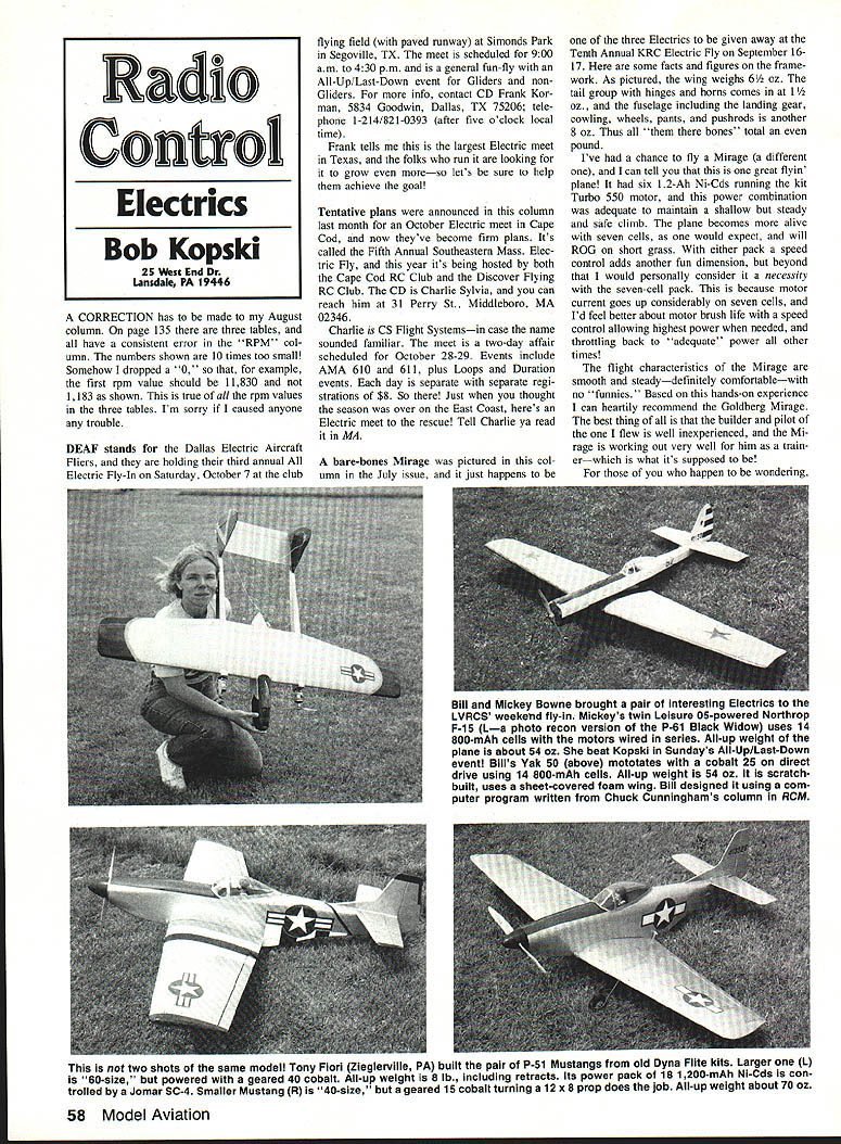
- Bill (Mickey) Bowne brought two interesting electrics to the LVRCS weekend fly-in:
- Twin .05-powered Northrop P-61 (photo-recon Black Widow) using 14 × 800‑mAh cells; motors wired in series; all-up weight ≈ 54 oz.
- Yak 50 powered by a Cobalt 25 direct drive using 14 × 800‑mAh cells; all-up weight ≈ 54 oz. (Scratchbuilt sheet-covered foam wing; designed using Chuck Cunningham’s program.)
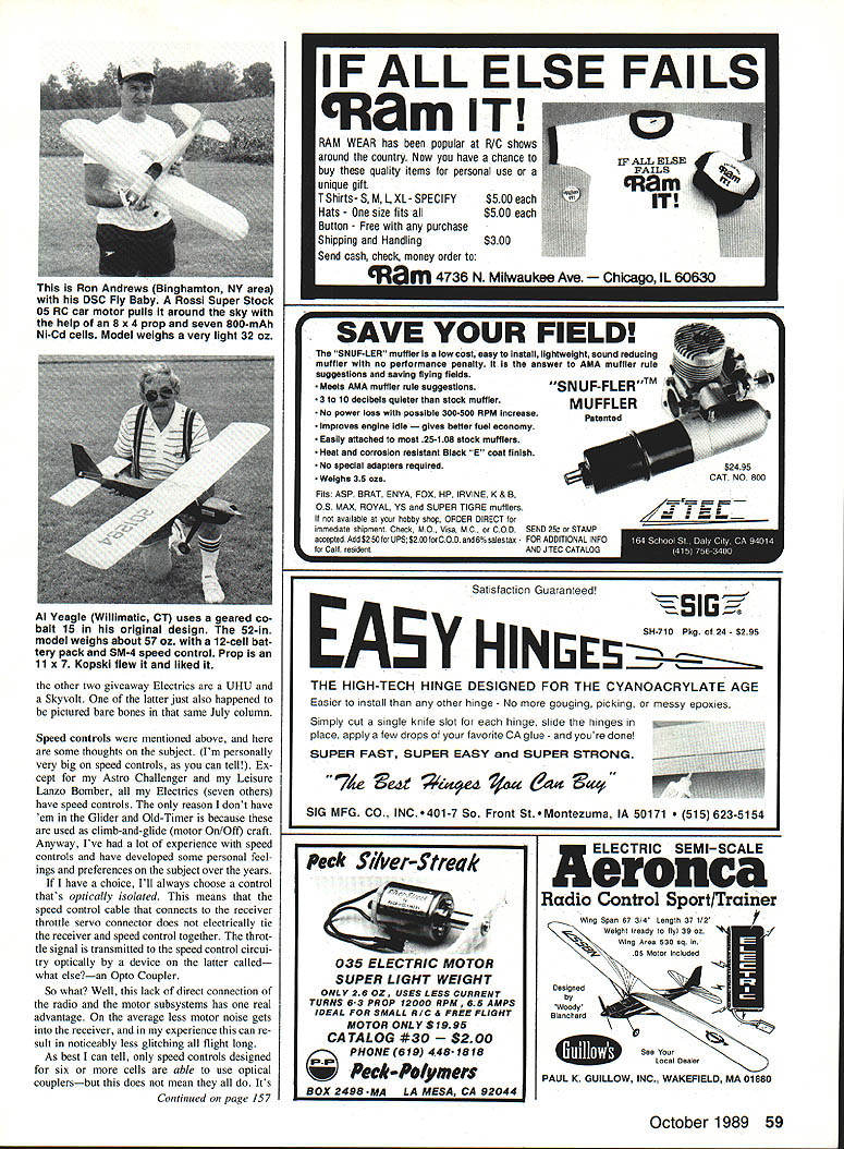
- Tony Fiori, Zieglerville, PA, built two P-51 Mustangs from old Dyna-Flite kits:
- Larger (L-60 size): geared .40 Cobalt, retracts, all-up ≈ 8 lb; power pack = 18 × 1200‑mAh NiCds, controlled by a Jomar SC‑4.
- Smaller (R-40 size): geared .15 Cobalt turning a 12×8 prop; all-up ≈ 70 oz.
- The other two giveaway electrics mentioned above are a UHU and a Skyvolt (the Skyvolt was also pictured bare-bones in July).
Speed controls
Opto-isolation and cell count
If I can choose, I prefer optically isolated (opto) speed controls. An opto speed control connects to the receiver throttle servo lead but is not electrically tied to the receiver; the throttle signal is transmitted optically by an opto coupler. The real advantage: less motor noise gets into the receiver, which in my experience reduces glitching during flight maneuvers.
However, opto-isolated controls generally require the motor battery to provide enough voltage for MOSFET gate drive — typically around 6 V or a little more. Speed controls intended for use with fewer than six cells often must use the receiver battery in some way to raise gate-drive voltage, so they cannot be opto-isolated and must be hard-wired to the receiver. This explains why some low-cell-count speed controls are more prone to glitches.
High-rate vs. frame-rate controls
- High-rate type: uses a high switching rate of power on/off (pulse-width modulation) to proportionally control the motor. This typically produces an audible whine or "singing" in the motor at low throttle settings. I prefer high-rate units for smoother control.
- Frame-rate type: uses the transmitter frame timing (around 50 Hz) and charges an internal capacitor to develop gate-drive voltage. Frame-rate units can be opto-coupled because they derive gate-drive voltage from the main motor battery, but they tend to be less smooth at low throttle settings and can have coarser control resolution.
Manufacturers usually indicate the control type in the instructions, but the surest way to know is to ask or consult someone who has used the unit.
My practical choice:
- For more than six cells: opto-isolated, high-rate type.
- For six cells or less: frame-rate units (accepting the limitations).
MOSFET mounting and adjustments
I prefer speed controls with these features:
- All MOSFET mounting tabs attached to a common metal heat sink. MOSFETs wired in parallel are unlikely to share current equally; a common heat sink helps equalize temperatures and improve sharing.
- Two adjustments for throttle: one to set the point where power begins (trim) and another to set full-power limit. These two adjustments are interactive but allow precise matching to stick travel.
- Ease of installation: mounting provisions and strain relief for the receiver lead-out wires (not just a solder joint).
- Enclosed electronics: avoid exposed printed circuit boards that can misbehave when damp.
Speed-control designs are improving (smoother low-end control, better thermal protection, smaller packages), but installation quality matters: good wiring practice, routing motor wires away from the receiver, and using proper connectors are important.
Motor mounting and cooling
Strap clamp mounting
In July I introduced a motor-mount method using wooden V-blocks on a ply mounting plate and two straps made from Perma-Gold (Sullivan Golden Rod) material tightened with 2‑56 screws. I’ve used it in several planes (including a .40-powered Exciter) and it has been trouble-free — almost.
In some installations where the motor case gets very hot the straps can stretch slightly and the motor may loosen a bit. I found no clamp failures; the remedy is routine attention to the draw-screw tightness and attention to airflow over the motor.
Battery and motor cooling experiment
I ran a small experiment using my Skyvolt (Cobalt .15-powered) to quantify the benefit of airflow through the battery pack.
- Battery: 12 × 900‑mAh cells (arranged to allow airflow between cells).
- Procedure: flights with the air intake open vs. blocked; between flights I forced the pack closed during/after charging so each flight began with relatively cool batteries. Temperatures measured with probes on several cells (negative ends) before and after flight and on the motor rear-end bell after flight. Flights were fairly aggressive and lasted up to a few minutes.
Results:
- With designed airflow: after-flight cell temperatures averaged about +13°C (+23°F) above before-flight temperatures.
- With intake blocked: after-flight cell temperatures averaged about +22°C (+40°F), with absolute values reaching as high as 65°C (149°F).
- Postflight motor housing temperatures varied between about 80° and 90°C.
Conclusions:
- Directed airflow through the battery pack significantly reduces cell temperature rise (on the order of 9°C in these tests).
- Motor temperatures can be high (80–90°C) and, in some installations, this heat may contribute to slight stretching of metal strap clamps. Pay attention to airflow around both motor and battery.
These were preliminary results from one installation; I plan more testing with other installations. Meanwhile, I continue to design for airflow through and around battery packs and to monitor motor mounting tightness.
Closing
Speed controls and good thermal management make a big difference in electric-flight performance and equipment longevity. Keep an eye on installation details — mounting, wiring, airflow — and you'll get more reliable, enjoyable flying. More experiments and observations to come.
Transcribed from original scans by AI. Minor OCR errors may remain.

