
Radio Control: Electrics
Bob Kopski 25 West End Dr Lansdale, PA 19446
This month's topics
- Electric Connection Service
- Electric meets
- Wiring connector losses
- New speed controls
- Electric technical journal
- My latest Electric — Senior Skyvolt
- A way to view "power"
Electric Connection Service
YOURS for the asking: the Electric Connection Service. Anyone or any club seeking electric modelers in their immediate area need only send me your info in writing, and I'll print it here.
As I'm writing this column, the January 1990 issue has just appeared in my mailbox, and it's the first one which mentions this service to the public at large. I'll hope by the time I write for the April issue I'll have more reader input resulting from this January introduction. Come on! I know you loners and E-clubs are out there!
Electric meets
In the same nature as the preceding, I'd like to offer some column space to list annual electric meets. In the past, several readers who wanted to schedule annual gatherings have inquired about other such known meets so as to avoid schedule conflicts. Thus, I'd like to invite groups having such annual plans to let me know as soon as possible, and I'll pass the info along right here.
To help start this off: the Annual KRC Electric Fly is scheduled for the third weekend of September. This year that's the 15th and 16th of the month.
This is not to leave out anyone with a first-ever event, or meets that do not hold the same annual date. If you send me the info in adequate time, I'll list it also. My primary thrust, however, is to help those more major annual activities avoid collision, since we might presume that annual meets are known—but just not to everyone!
Wiring and connector power losses
Wiring and connector power losses were a topic covered in this column back in December 1987, and in the electric columns of the other model magazines about the same date. That coverage was based on some rather extensive work performed by Keith Shaw and shared with several writers. In this work, Keith measured the losses of several popular connectors and wire types and presented the results.
Recently a friend approached me with a problem installation. He felt that his speed control was causing the loss of about 1,000 rpm on his Cobalt .15 at the full-on condition, so I agreed to check it out. What I found was that such was not the case at all! Yes, he had a lot of voltage loss in the installation—about a volt (!)—but not in the speed control. Very nearly all the loss was in the connectors!
That experience reminded me of Keith's work and prompted me to do some additional similar work. In particular, one of the connectors in my friend's plane (and some that I use myself) was not included in Keith's original tables, so I wanted to get detailed info for those. Then, for the sake of continuity, I repeated some that Keith evaluated.
Test setup
- Wire used: high-flexibility Jomar 16-gauge (recently upgraded to 15-gauge).
- Connector sets were connected in series.
- Current source: electronically regulated constant-current source set to 10.0 amps through the string.
- Voltage probes: straight pins stuck through the wire insulation served as probes (tiny holes are negligible and pose no exposure risk).
- Measurements: a DVM (digital voltmeter) connected to pins spaced six inches apart measured voltage drops. Connectors were located about the middle of each six-inch spread.
- A straight length of wire with no connector was included to serve as a reference; that result was subtracted from subsequent measurements to yield connector losses alone.
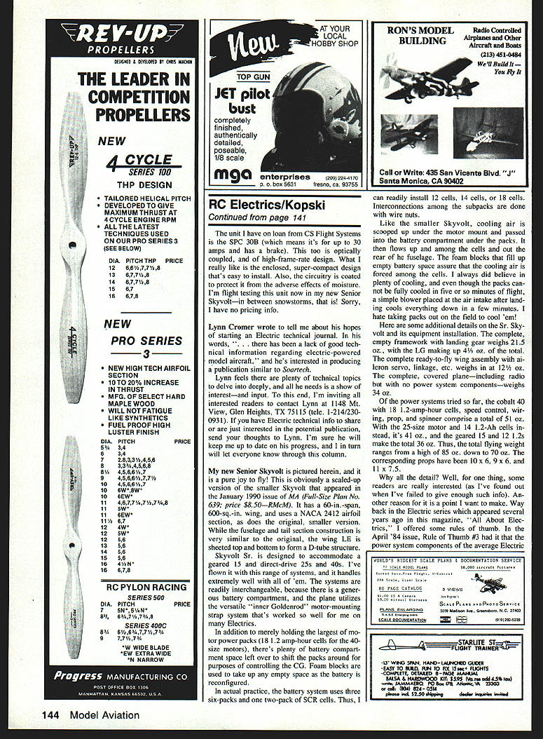
- Connectors tested: wire nut, male/female crimp, Sermos, Tamiya (both conductors measured separately), and a 25-amp ATC fuse connected to crimped-on female connectors. Both conductors were measured separately where applicable.
Measured and calculated results
(Note: "m" = milli = 0.001. Thus 0.082 millivolts = 0.000082 volts.)
- 6-in. wire — Total Loss: 22.1 mV — Net Loss: 22.1 mV — Resistance: 4.42 milliohms — Keith's result: 4.44 milliohms
- Tamiya — Total Loss: 37.8 mV — Net Loss: 15.7 mV — Resistance: 1.57 milliohms — Keith's result: 1.44 milliohms
- Sermos — Total Loss: 25.9 mV — Net Loss: 3.8 mV — Resistance: 0.38 milliohms — Keith's result: 0.27 milliohms
- Crimp — Total Loss: 150 mV — Net Loss: 128 mV — Resistance: 12.8 milliohms — Keith's result: N/A
- Fuse (25 A ATC) — Total Loss: 185 mV — Net Loss: 163 mV — Resistance: 16.3 milliohms — Keith's result: N/A
- Wire nut — Total Loss: 30.4 mV — Net Loss: 8.2 mV — Resistance: 0.82 milliohms — Keith's result: N/A
Notes and conclusions on connectors
- It is quite clear that the best connectors continue to be Sermos.
- My friend had quite a few crimp pairs in his installation — so you can see what this problem was. There was more drop across one crimp pair than on his speed control.
- As always, the ever-necessary fuse will cost some loss no matter what.
- The lowly wire nut is not all that bad: it's cheap, compact, and readily available.
Comparison to Keith Shaw's results
Keith's numbers are generally to be preferred where available. I had some known experimental error associated with the exact measurement of wire length, as it involved the physical portion of wire in and near the connector itself; in many cases the actual length was somewhat more than the intended six inches, so the voltage drops would be higher than expected. Whatever you do, be wary of installation losses in your plane. Use quality wire and quality connectors—but use them sparingly!
New speed controls
Two new speed controls are shown in photos this month.
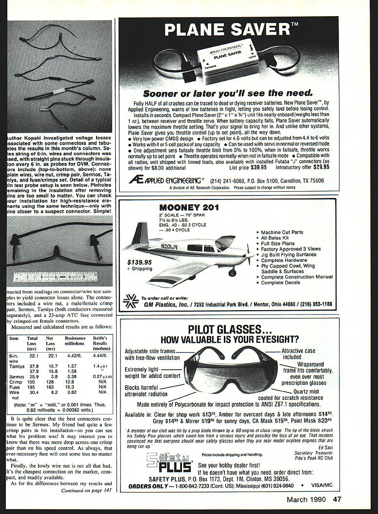
- Jomar SC 6 (prototype shown) — a large control for big systems. Mentioned as an upcoming product in my December 1989 column, the SC 6 is now closer to reality. It is designed to operate with 22–34 cell systems and features a new Signetics chip designed to drive MOSFET gates efficiently. It is a high-frame-rate design with ample thermal capacity. Tentative list price is $130; wider distribution and competition should reduce this price.
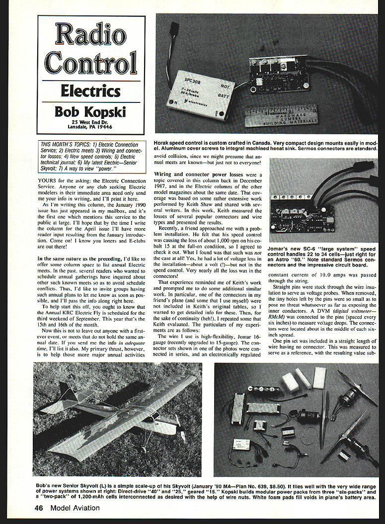
- Horak (imported from Canada) — hand-made by Jiri Horak (3403 Fellmore Drive, Mississauga, Ontario, Canada L5C 2E1) and in scarce supply. Jiri makes several versions, including ones with brakes.
The unit I have on loan from CS Flight Systems is the SPC 30B (for up to 30 amps with brake). This too is optically coupled and of high-frame-rate design. I like the enclosed, super-compact design that's easy to install. The circuitry is coated to protect it from moisture. I'm flight testing this unit now in my new Senior Skyvolt. Sorry, I have no pricing info.
Electric technical journal
Lynn Cromer wrote to tell me about his hopes of starting an electric technical journal. In his words, "there has been a lack of good technical information regarding electric-powered model aircraft," and he's interested in producing a publication similar to Soartech. Lynn feels there are plenty of technical topics to delve into, and all he needs is a show of interest—and input.
If interested, contact Lynn at: Lynn Cromer 1148 Mt. View Glen Heights, TX 75115 Tel: 1-214-230-0931
If you have electric technical info to share or are just interested in the potential publication, send your thoughts to Lynn. I'll keep readers up to date on his progress.
My latest Electric — Senior Skyvolt
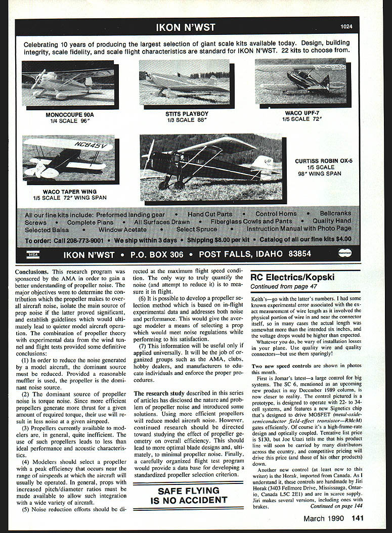
My new Senior Skyvolt is pictured herein, and it is a pure joy to fly! This is a scaled-up version of the smaller Skyvolt that appeared in the January 1990 issue of MA (Full-Size Plan No. 639; $8.50). It has a 60 in. span, 600 sq. in. wing, and uses a NACA 2412 airfoil section, as does the original. Fuselage and tail construction are similar to the original; the wing is sheeted top and bottom to form a D-tube structure. Skyvolt Sr. is designed to accommodate geared and direct-drive 25s and 40s. I've flown it with this range of systems, and it handles extremely well with all of them.
Features and construction notes:
- Generous battery compartment with easy interchange of systems.
- Uses the inner Goldencord motor-mount strap system.
- Battery system uses three six-packs and one two-pack of SCR cells, allowing installation of 12, 14, or 18 cells. Interconnections among subpacks are done with wire nuts.
- Cooling: air is scooped up under the motor mount and passed into the battery compartment under the packs; foam blocks force air among the cells. Packs stay significantly cooler than on the smaller Skyvolt.
Weights and systems tested:
- Empty framework with landing gear: 21.5 oz (LG is 4.5 oz of that).
- Complete ready-to-fly wing assembly (including radio, excluding power system): 34 oz.
- Cobalt 40 system (18 × 1.2-Ah cells, speed control, wiring, prop, spinner): 51 oz.
- 25-size motor with 12 × 1.2-Ah cells: 31 oz.
- Geared 15 with 12 × 1.2-Ah cells: 30 oz.
- Flying weight range: 85 oz (high) down to 70 oz (low).
- Corresponding props used: 10×6, 9×6, 11×7.5.
A note on power fraction: Way back in the Electric series "All About Electrics" (April 1984), Rule of Thumb #3 said the power system components of the average electric model make up about 50% of the total model weight. Reasonable limits are 40% to 60% (i.e., 50% ± 10%). The power systems above comprise 60%, 55%, and 52%, respectively. These higher values are typical for aerobatic-type planes; glider configurations run lower.
Flight impressions: So far all flight tests occurred in outside temperatures of 32° to 40° F and mostly with a strong breeze, but all flights have been pure pleasure. Like the smaller version, the big Skyvolt handles very nicely inverted; inverted climbs, loops, square loops, outside loops, Immelmanns, stall turns, rolls, etc., are easy. Ground handling is very good for a tail-dragger, and takeoff runs are very short—shortest with the 40. I feel like building another just to prove this good performance is no accident!
A way to view "power"
Some readers might ask: "How can the same plane fly so well on both a 15 and a 40?" Put simply, terms like "15" and "40" mean absolutely nothing without context. Here's a way to view the matter:
- All installations used 1,200-mAh cells (even though the 15 is normally packaged with 900s).
- Suppose we want a flight of exactly five minutes. On average the battery current drawn for that flight might be about 15 amps.
- Motor input power on average then is roughly voltage × efficiency × current. For example:
- 12 V × 1.1 × 15 A ≈ 200 watts (example for the 15)
- 18 V × 1.1 × 15 A ≈ 300 watts (example for the 40)
- Ratio ≈ 1:1.5 in this example, while weight ratio might be only 1:1.21 (85/70).
- Thus the practical power spread and weight range make the "15-to-40" argument less significant for typical flying described (cruising with short bursts). The 40 still can develop more peak power and has more punch, but a properly geared and propped 15 with the right pilot technique can do very well.
I am not saying the 15 and the 40 are nearly equal—only that thinking in terms of watts and real operating conditions is far more useful than relying on motor-size nomenclature. Motor descriptions and specifications need to mature beyond the current shorthand.
Final notes
Now it's back to building, 'cause spring is comin'—I hope! Please forward any comments or questions (with SASE) to me at the address shown in the column header.
Happy Electric Landings, everyone.
Bob Kopski
Transcribed from original scans by AI. Minor OCR errors may remain.

